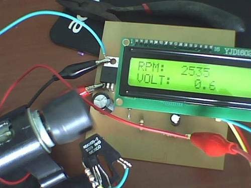
Hey friends, I should have posted this project last month itself but there was some problem with the circuit. [link], author of this project did an exellent job. I have been watching him learning on this website. He came as a total noob but now he is well versed with 8051 and PIC microcontroller. earlier he has submitted Microcontroller Based Home Security System
This project is about A Contactless Digital Tachometer. As per defination from wikipedia
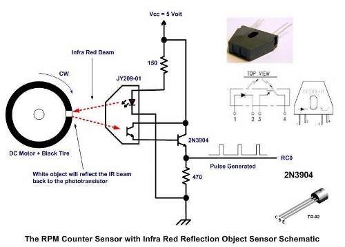
Following diagram explains the logic of this project.
The infra red reflective object sensor work by simply emitting the infra red beam and when it encounter the white object surface than the infra red beam will be reflected back to the phototransistor; next the phototransistor and the 2N3904 transistor which formed the Darlington pair will start to conduct and will generate enough voltage across the 470 Ohm resistor to be considered by the PIC16f690 microcontroller build in Capture Compare Pulse width modulation(CCP )module input port as the logical “1”. When the infra red beam encounters the black tire surface than both of the phototransistor and 2N3904 transistor will turn off; and the voltage across 470 Ohm resistor will drop to 3.5 volt (logical “0”).
Therefore by timing the generated pulse period by the infra red reflective object sensor we could easily calculate the RPM using this following formula:
Frequency = 1/T Hz; T is the generated pulse period in second.
RPM (Rotation per Minute) = Frequency x 60
Here is a sample video of working project:
You can download project related files here:
Download Contactless Digital Tachometer project
Thank you Romel for this contribution. If anyone has doubts regarding this project, please use forum.
For more detail: Contactless Digital Tachometer using PIC Microcontroller


