Summary of The 2$ USB Pic Programmer & Serial Cable
This article describes a low-cost DIY PIC microcontroller programmer using a USB virtual COM port module and basic electronic components. It is designed for infrequent users, as the programming process takes 5–30 minutes. The guide details circuit assembly, software configuration using PICPgm in JDM mode, and troubleshooting counterfeit PL2303HX chips.
Parts used in the 2$ USB Pic Programmer:
- USB virtual com port module or cable with DTR, CTS and RTS
- NPN Transistor (BC547B or BC338)
- 1 x 4.7 Kohm Resistor
- 2 x 10 Kohm Resistor
- STABLE 12 volt power supply
- Wires and soldering iron
- PICPgm Software
This programmer is intended for people who need a microchip pic programmer to flash at hex file onto a micro controller, but seldom do so and find investing in a pic kit of some sort too expensive. The programming process will take a long time, 5-30 min depending on hex file size, so its NOT recommended for microchip software developers.
What you need:
USB virtual com port module or cable with DTR, CTS and RTS.
1 x NPN Transistor etc. BC547B or BC338
2 x 10 Kohm Resistor
1 x 4.7 Kohm Resistor
A STABLE 12 volt power supply
Some wires a soldering iron
Step 1: The Circuit
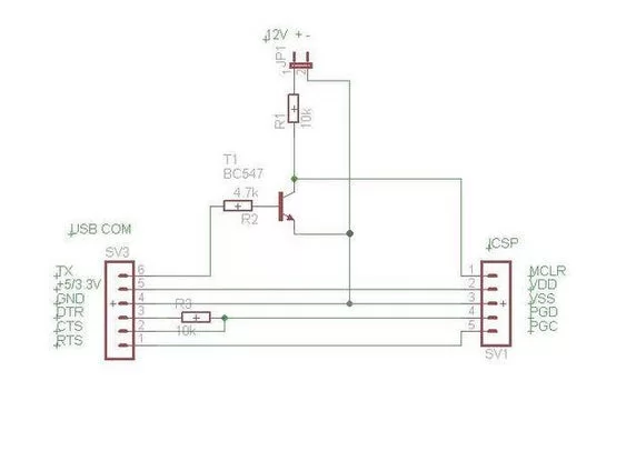
This simple circuit will work with the free programmer software PICPgm
selecting it to operate as an JDM programmer.
Check out the the amazing numbers of supported devices and the software is available for Windows, Mac OS and Linux.
The second circuit makes the USB com both an programmer and a standard serial cable.
Update:
As pointed out by dev26th in comment section:
Connect MCLR with a 10k. resistor to Ground.
This prevents MCLR from floating.
Step 2: The USB Virtual Com Port
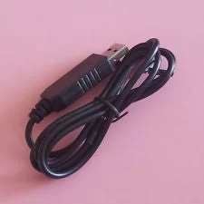
My solution is based on the 2 $ USB virtual com port chip PL2303HX CABLE from ebay see it here
As seen on ebay there is a housing and you cant see the available pin outs. The housing opens easely. My cable came with the following pins TX,RX, +5V, +3.3V, Ground, RTS, DTR, DSR, CTS, DCD, but you need to ask seller which pins are available to be sure.
All other USB com modules with the RTS, DTR, CTS pins available will work.
20.5.2015 Note: Some time after publishing this instructable I became aware that some of PL2303HX chips on the marked are counterfeit. I tested this instructable on XP machine and had no problems and therefore not aware of this. I installed a custom hardware solution on another computer running windows 8.1 with another cable and realized that cable was counterfeit.
If you bought a counterfeit model and you are having driver issues, the driver error code will most likely be 10. If you google the chip number and the error code you will find a solution to make it work. I’m sorry for this issue, I don’t support counterfeit.
Step 3: The SMD Hack
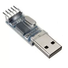
This even cheaper module as the picture shows, can be used if you can solder on smd chips. Remove the plastic and look for the dot which is pin 1. Solder wires on pin 2, 3 and 11.
Step 4: PICPgm Software
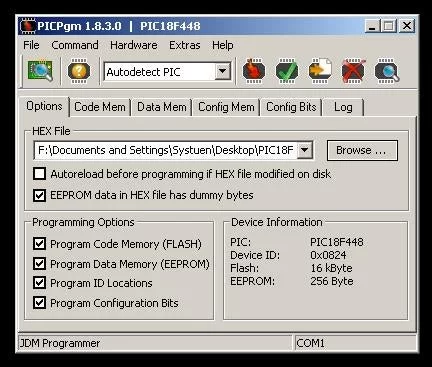
As the picture show I have successfully recognized a PIC18F448
Step 5: PICPgm Settings
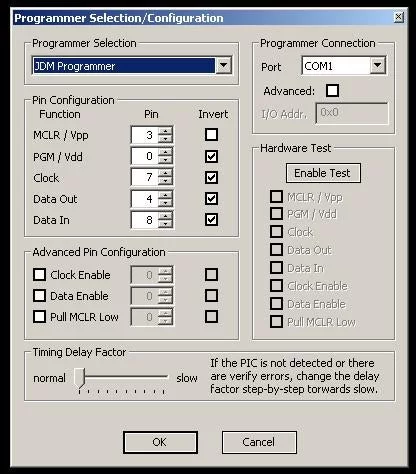
In Hardware Settings choose JDM programmer, the correct com port. Invert all pins except MCLR.
You now have a functional ICSP programmer. Good Luck
Source: The 2$ USB Pic Programmer & Serial Cable
- Who is this programmer intended for?
It is intended for people who need a microchip pic programmer but seldom do so and find investing in a pic kit too expensive. - How long does the programming process take?
The process takes 5-30 minutes depending on hex file size. - Is this recommended for microchip software developers?
No, it is NOT recommended for microchip software developers due to the long programming time. - What software is required to operate this circuit?
You must use the free programmer software PICPgm selecting it to operate as an JDM programmer. - Which pins are essential on the USB virtual com port?
You need a module with DTR, CTS and RTS pins available. - How do you prevent MCLR from floating?
Connect MCLR with a 10k resistor to Ground. - What error code indicates a counterfeit PL2303HX chip?
The driver error code will most likely be 10 if you bought a counterfeit model. - Which pins should be soldered when using the SMD hack module?
Solder wires on pin 2, 3 and 11 after locating pin 1 marked by a dot. - What hardware setting is required in PICPgm?
In Hardware Settings choose JDM programmer, the correct com port, and invert all pins except MCLR.