Summary of SMART STATION
The Smart Station is a PIC32-based home hub featuring environmental sensing and music-adaptive entertainment. It monitors temperature, humidity, light, and motion via I2C sensors, displaying real-time graphs and threshold alerts on a TFT screen. A NeoPixel ring reacts to audio beats captured by a microphone, while Bluetooth connectivity allows music control. The system is housed in a custom 3D-printed enclosure with a perf board for modular connections.
Parts used in the Smart Station:
- PIC32MX250F128B microcontroller
- 3.5mm jack for speakers
- TFT display
- Keypad
- NeoPixel LED ring
- Microphone
- I2C accelerometer breakout
- I2C temperature sensor breakout
- I2C humidity sensor breakout
- I2C luminosity sensor breakout
- RN-52 Bluetooth Module
- TI CD4501B multiplexer
- 3D printed casing
- Perf board
INTRODUCTION
Our Smart Station hardware consists of a PIC32MX250 microcontroller with a 3.5mm jack for speakers, a TFT display, keypad, NeoPixel LED ring, microphone, and a host of I2C environmental sensor breakouts: i.e. accelerometer, temperature, humidity, and luminosity sensor breakouts. All of the electronics are neatly contained within a 3D printed casing. Our Smart Station system has two main features: environmental sensing and entertainment. The device is capable of displaying readings for all of the sensor peripherals on a continuously-updating graph display. Additionally, the device features a setting screen which allows users to input high and low threshold values for each sensor peripheral so that if the sensor reads in values outside of the provided range, alerts are displayed on the NeoPixel LED ring on the top of the device. On the setting screen the user can also manipulate the color of the selected sensor on the real time graph plot. Once a sensor is selected on the settings screen, returning to the graphing screen will display that specific sensor’s information, including the sensor’s name, the current value, a line graph of the data being read, and horizontal lines indicating the user-input triggering thresholds. Finally, our device features a music-adaptive entertainment console which can connect to any Bluetooth audio source using the RN-52 Bluetooth Module. Using UART commands, the PIC32 can send media button commands like pause and track skip to the RN-52 module to control the music output from an external Bluetooth device. Using feedback from the system’s built-in microphone, the device is capable of generating a unique light show on the NeoPixel LEDs which pulsate and change colors according to beats from music that is output to the speakers.
HIGH LEVEL DESIGN
OVERVIEW
Our decision to work on this project stemmed from our mutual interest in remote sensing and control applications. When formulating project ideas, we came up with the plan to build a home base station that would alerting the user based off of certain sensor triggers. This idea evolved to include an entertainment feature after looking into the design of commercial smart stations like the Amazon Echo. To do this we added the ability to play back music and display an interactive light show using a NeoPixel LED ring. This project presented a multitude of hardware and software design challenges. Given the large number of sensors and peripherals we wanted to include, it was a challenge to properly organize them within our custom 3D printed housing in a neat and compact way. On the software side, we were faced with the challenges of setting up and creating our own PIC32 library to implement I2C protocol for all the sensors, creating a UART control API for the RN-52 Bluetooth module, as well as designing assembly code in order to bit-bang the NeoPixel LED ring with correct timing requirements.
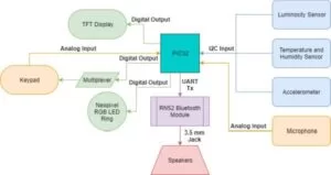
HARDWARE BLOCK DIAGRAM
The diagram above showcases all of the peripherals utilized in this project, as well the protocols that were used to interact with them. When all of our devices were finally wired in, we had used all but four peripheral pins on the PIC32MX250F128B. The configuration of the I2C, UART, digital outputs, and analog inputs also contributed to the overall complexity of our final firmware design.
HARDWARE
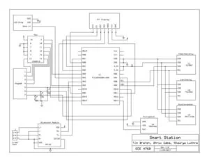
SCHEMATIC
The schematic below showcases all of the peripherals connected to the pins on the PIC32 chip. One problem that we ran into that we discovered was located in the PIC32 errata for this specific chip was that, if I2C1 is enabled, all digital output-only functions and all analog functions on pins RA0 and RA1 do not function properly. We worked around this issue by using a multiplexer (TI CD4501B) and having all of the analog keyboard outputs be generated from 1 analog pin instead of 4, as in Lab 2. Another important thing to note about our hardware is that the NeoPixel LED is designed for 5V logic, but can still be operated using PIC32’s 3.3V logic level. Datasheets and further information on each piece of hardware may be found in the appendix.
3D PRINTED ENCLOSURE
The purpose of the 3D printed enclosure was to properly house all the electronics, hiding the bundles of wires and the microcontroller while leaving only the necessary peripherals accessible: i.e. the TFT display, keypad, power supply port, and 3.5mm jack for the speakers. In early stages of this project, our intention was to use an ultrasonic distance sensor that would serve as a wakeup for the system. While working through the project, we discovered that the sensor used a 5V logic level as opposed to the 3.3V operating level of the small board we were working off of. Instead of implemented logic level-shifting circuitry, we decided to include a microphone and NeoPixel LED ring. For that reason, the CAD model and our 3D print had an extraneous opening for the ultrasonic sensor which was not necessary, and was lacking an opening in the back in which the wires for the microphone and the LED ring would rest. The extraneous opening was covered with black electrical tape to make it appear solid, and a notch was cut out in the back of the box with a dremel for the additional wires. Below are images of the first version of the CAD, the physical unit, and then the potential update to the CAD model.
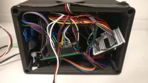
PERF BOARD
The design of the perf board was most complex part of the hardware design of this project. In order to have all of the electronics fit nicely within the enclosure, a great deal of soldering and planning needed to be done. A separate perf board was used to connect all of the pins of the small board housing the microcontroller. These pins were broken out and sent to headers that were connected to sensors and modules. On this perf board, there were the in-line and pull-up/pull-down resistors for the keypad, all the SDA and SCL lines for the I2C protocol sensors, and all other I/O peripheral pins. Our intention was to keep the design as modular as possible, and for that reason, header pins were heavily utilized to facilitate simpler debugging of individual sensors and peripherals. Below is the perf board with all the electronics housed within the enclosure.
HARDWARE RESULTS
Ultimately, we feel that our final hardware design came together very well. As we developed our project, we sometimes had to pivot when we ran into roadblocks like the distance sensor requiring 5V instead of 3.3V, or when we were lacking pins two analog pins due to the fabrication error described in the errata of the PIC32 datasheet. The product came out clean, organized, and kept all the electronics securely housed within the enclosure. If we were to do the project again, we have some ideas on areas which we would like to have improved on. As previously discussed, the casing can be changed, not only to have the appropriate cutouts, but also make a sleeker, less boxy design. Additionally, the port opening for the 3.5mm jack and the power cable were a bit tight and needed to be sanded away so having a more open port design may benefit the system not only for functionality, but also aesthetically. Furthermore, different colors could be used for a friendlier look, and the 3D print could have been chemically bathed or sanded further to create a more polished look. Overall, functionality-wise, the hardware functioned exactly as we had intended, but aesthetically, we felt that it could have been improved.
SOFTWARE
CONFIG.H
The config.h header file includes the ‘plib.h’ library, and contains only a few defines for the project. Namely, it sets the oscillator source to be the 8MHz internal oscillator of the microcontroller, sets the div FPLLIDIV to be 2, the prescalar ‘FPLLMUL’ to 20, and the div’s ‘FPBDIV’ and ‘FPLLODIV’ to be 1 and 2, respectively. This combination of the divisions and multipliers generates a 40MHz system clock source and sets the peripheral bus frequency to be 40MHz.
MAIN.C
The main function within main.c sets up all of the I/O pins used within the project, initializes the ADC and I2C modules, outputs the main menu screen to the TFT display, and sets up I2C transactions between the PIC32 and the accelerometer and luminosity sensor peripherals. First, the main function calls adc_setup() which sets, opens, and enables pin AN11 for analog microphone readouts using the following configuration parameters:
// Ensure the ADC is off before setting the configuration
                    CloseADC10();

                    // ADC_FORMAT_INTG16       Use this in order to get unsigned 16 bit integers
                    //
                    // ADC_CLK_AUTO            This allows for converting the samples immediately
                    //                         after they are read in
                    //
                    // ADC_AUTO_SAMPLING_OFF   By setting this, sampling is done when the user
                    //                         wants rather than once the previous sample is done
                    //                         converting
                    //
                    #define PARAM1  ADC_FORMAT_INTG16 | ADC_CLK_AUTO | ADC_AUTO_SAMPLING_OFF

                    // ADC_VREF_AVDD_AVSS      Set the voltage references to the same as that of
                    //                         the PIC32 rather than other external references
                    //
                    // ADC_OFFSET_CAL_DISABLE  We don't want to do the extra steps in order to
                    //                         configure perfect precision as the movement of the
                    //                         paddle is highly relative
                    //
                    // ADC_SCAN_OFF            Scan mode is disabled because we don't have a
                    //                         vector of inputs to scan through but rather just
                    //                         the one
                    //
                    // ADC_SAMPLES_PER_INT_1   Only take one sample per interrupt rather than
                    //                         more. We only need to know how the paddle moves
                    //                         once per event
                    //
                    // ADC_ALT_BUF_OFF         Buffer configured as one 16-word buffer rather
                    //                         than two 8-word buffers
                    //
                    // ADC_ALT_INPUT_OFF       Always use MUX A input multiplexer settings rather
                    //                         than switching between MUX A and MUX B
                    //
                    #define PARAM2  ADC_VREF_AVDD_AVSS | ADC_OFFSET_CAL_DISABLE | ADC_SCAN_OFF | \
                                    ADC_SAMPLES_PER_INT_1 | ADC_ALT_BUF_OFF | ADC_ALT_INPUT_OFF

                    // ADC_CONV_CLK_PB         Use the peripheral bus clock
                    //
                    // ADC_SAMPLE_TIME_5       Used to properly set acquisition time
                    //
                    // ADC_CONV_CLK_Tcy2       Divide the peripheral bus clock by two in order to
                    //                         run it at the highest rate using its 8-bit counter
                    //
                    #define PARAM3 ADC_CONV_CLK_PB | ADC_SAMPLE_TIME_5 | ADC_CONV_CLK_Tcy2

                    // ENABLE_AN11_ANA - enables pin 24 to be our input for the ADC
                    #define PARAM4 ENABLE_AN11_ANA

                    // SKIP_SCAN_ALL - don't set any channels to scan
                    #define PARAM5 SKIP_SCAN_ALL

                    // ADC_CH0_NEG_SAMPLEA_NVREF  Sets the negative input of the MUX to the
                    //                            negative reference of the PIC32
                    //
                    // ADC_CH0_POS_SAMPLEA_AN11   Sets the positive input select to be AN11
                    //
                    SetChanADC10(ADC_CH0_NEG_SAMPLEA_NVREF | ADC_CH0_POS_SAMPLEA_AN11);

                    // Configure ADC using the parameters defined above
                    OpenADC10(PARAM1, PARAM2, PARAM3, PARAM4, PARAM5);

                    // Enable the ADC
                    EnableADC10();
After initializing the ADC for the microphone peripheral, the main function initializes the TFT display and sets up pin RA2 as a digital output for the data in line of the NeoPixel LED ring. The function then calls the sensors_setup function, which initializes a global array of sensor structs with the following attributes for each sensor peripheral: name, maximum possible value, minimum possible value, high trigger value, low trigger value, and plot color. By default, the high and low trigger values were chosen so that, during our demo, we could interact with the sensors and cause them to trigger on certain events (i.e. shining a phone light on the luminosity sensor or breathing on the humidity sensor). After initializing the sensor struct, the main function then uses the i2c_rw.h driver, discussed below, to write registers that initialize I2C transactions with the accelerometer and luminosity sensors. Afterwards, the main function calibrates the accelerometer by performing a series of I2C reads and determining the appropriate constants for zeroing out the x, y, and z-acceleration readouts. Lastly, the main function calls a method which makes the NeoPixel LED ring at the top of the device turn blue before scheduling all of the program threads.
The pt_measure thread is responsible for calling of the sensor update functions and storing the new readings in the global array of current sensor values. This function reads out current microphone analog input voltage and squares it to obtain a sufficient statistic for the power output of the speaker. The program then averages the readout with the past 10 sensor readouts and stores the average power in a global variable that is used for reactive lighting in the pt_led thread. After calculating the sufficient statistic for the average mic power, the thread then calls the i2c_rw functions for the accelerometer, temperature, humidity, and luminosity sensors. These methods are described in extensive detail in the i2c_rw.h section, as well as within the comments for the file.
The pt_led thread contains all of the necessary logic for toggling between reactive music mode and idle modes depending on the current state of the device and the current power output of the mic. When the thread is first entered and the user is on the music screen, the NeoPixel LED ring will remain solid red until the first power spike in the speaker output. Once this peak is detected, the LED will alternate between one of three color states with varying levels of either red, green, and blue RGB values – with each state being based on the magnitude of the power spike (lower power spikes lead to more neutral coloring while higher power spikes lead to sharper coloring). Additionally, between any two power spikes, the direction in which the new color sweeps across the NeoPixel LED ring is reversed, creating a back and forth motion effect. Whenever the average mic power is below a specified threshold value, the NeoPixel LED ring will remain a solid color.
The protothread_input contains all of the necessary logic for reading/debouncing keypad values and performing actions on the device according to current menu that the device is in: either the main screen, the settings screen, the music screen, or the graph screen. The keypad readout code is based off of the example project located in the ZIP file on the index_TFT_display page of the ECE 4760 website. Initially, the thread declares the length 12 keytable array containing all of the various key encodings and initializes the input and output pins on the keypad. The keypad array is in order from 0-9, followed by * and #, where the absence of a valid key press is encoded by the index -1. In the while-loop for this thread, each row of the keypad is read out by driving the analog output A0 which is input to a demultiplexer, changing the demultiplexer control signal to switch between one of the first four input pins on the keypad, and reading the outputs on the keypad pins 6 through 8 which are connected to PIC32 digital input pins RB5, RB7, and RB10 respectively.
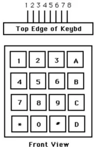
If any of the keys have been pressed, one or more of the digital inputs will detect a non-zero value which is compared with the entries in the keypad table. If there is a match, the index of the matched entry is stored in a variable. The index ‘-1’ encodes no match, ‘0-9’ encode digits 0 through 9, ‘10’ encodes *, and ‘11’ encodes #. In the debouncing state machine, there is a switch statement containing no push, maybe push, pushed, and maybe no push states. In order for a press to be registered as a valid button press and enter the pushed state of the FSM, the press must be detected for two consecutive executions of the keypad thread. The pressed state of the debug state machine contains a nested FSM where the each of the 4 screen states has its own independent switch-statement that defines what actions can be performed on that screen using the keypad buttons. The majority of these actions are simply for entering/exiting and inputting simple multi-digit integers, as performed in lab 2, with the exception of the music controls on the music screen.
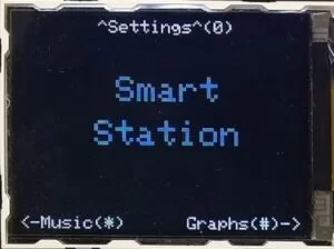
The menu screen contains 3 options. Pressing the 0 key on the keypad enters the settings screen, pressing the * key enters the music screen, and pressing the # key enters the graphs screen. From any other menu within the program, this main menu can be re-entered using the * key.
Source: SMART STATION
- What are the main features of the Smart Station?
The device provides environmental sensing with graph displays and alerts, plus a music-adaptive entertainment console with reactive lighting. - How does the device alert users when sensor values are out of range?
Alerts are displayed on the NeoPixel LED ring located on top of the device when readings exceed user-defined high or low thresholds. - Can the user change the color of the sensor data on the graph?
Yes, users can manipulate the color of the selected sensor on the settings screen which updates the real-time graph plot. - How does the device control music playback from an external source?
The PIC32 sends media button commands like pause and track skip to the RN-52 Bluetooth module using UART commands. - What causes the NeoPixel LEDs to pulse and change colors?
The lights react to beats from music output to the speakers, generating a unique light show based on feedback from the built-in microphone. - Why was a multiplexer added to the hardware design?
A TI CD4501B multiplexer was used to route analog keyboard outputs through a single analog pin because pins RA0 and RA1 malfunctioned when I2C1 was enabled. - What logic level does the ultrasonic distance sensor require?
The ultrasonic distance sensor requires a 5V logic level, which differed from the 3.3V operating level of the microcontroller board. - Does the NeoPixel LED operate at the same voltage as the microcontroller?
No, the NeoPixel is designed for 5V logic but can still be operated using the PIC32's 3.3V logic level.