Summary of RFID Interfacing with PIC Microcontroller
This article details a project to interface an RFID system using a PIC16F877A microcontroller and an EM-18 module. The setup reads unique IDs from passive 125 KHz tags and displays them on a 16x2 LCD, utilizing UART communication at 9600 baud. Applications include attendance, security, and voting systems.
Parts used in the RFID Interfacing with PIC Microcontroller:
- PIC16F877A
- EM-18 RFID Module
- 16x2 Character LCD
- 20Mhz Crystal
- 33pF ceramic disc capacitor
- 10k preset pot
- 4.7k resistor
- Breadboard
- Single strand wires
- 5V adapter
- 5V Buzzer
- 100uF capacitor
- .1uF capacitor
- BC557 Transistor
- LED
- 2.2k resistor
- 470R resistor
RFID stands for Radio Frequency Identification. RFID module can read or write small amount of data into a Passive RFID tag, which can be used in identification process in various systems like Attendance system, security system, voting system etc. RFID is very convenient and easy technology.
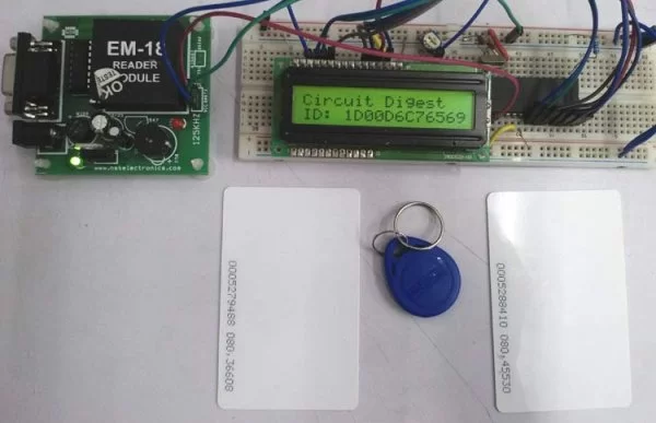
To read the Passive RFID cards and tag, we need a microcontroller with UART hardware. If we select a microcontroller without UART, we need to implement software UART. Here we are using PIC Microcontroller PIC16F877A for interfacing RFID. We will simply read the unique identification no. of RFID tags and display it on 16×2 LCD.
RFID module and its Working
In this project, we chose EM-18 RFID module, which is small-sized, low cost, and power efficient module. EM-18 RFID module use 125 KHz RF frequency to read passive 125 KHz RFID tags. EM-18 module use Oscillator, demodulator and data decoder to read data from a passive card.
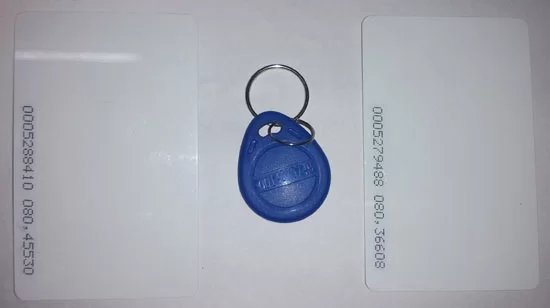
RFID Tag
There are three types of RFID tags available, Passive, Active or Battery-assisted passive. Different kind of RFID tags with a different kind of shapes and sizes are available in the market. Few of them use different frequency for communication purpose. We will use 125Khz Passive RFID cards which holds the unique ID data. Here are the RFID card and tags we are using for this project.
Working of RFID
The module uses UART communication protocol in 9600 Baud rate. When a Valid frequency tag is brought into the magnetic field of the EM-18 reader, the BC557 transistor gets on and the buzzer will start beeping, it also glows the LED. We are using a module which is easily available in the market and has complete circuitry with a buzzer, led, and an additional RS232 port.
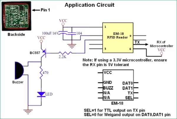
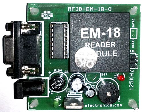
Here is the RFID board module we are using with pin names. This module also has additional power option.
One thing needs to be kept in mind that the output of EM-18 reader uses 5V logic level. We could use another microcontroller which uses a lower logic level, but in such cases, the additional logic level converter is required. In few cases, the UART pin of the 3.3V microcontroller is often 5V tolerant.
The UART output provides 12-bit ASCII data. First 10 bits are RFID tag number, which is the unique ID and last two digits are used for error testing. Those last two digits are the XOR of the tag number. EM-18 module will read the data from 125 KHz Passive RFID tags or cards.
Those tags or IDs have a factory programmed memory array which stores the unique ID number. As those are passive, so no battery is present in the card or tags, they get energized by the magnetic field of the RF Transceiver module. These RFID tags are made using the EM4102 CMOS IC which is clocked by the magnetic field too.
Material Required
To make this project we need following items-
- PIC16F877A
- 20Mhz Crystal
- 2pcs 33pF ceramic disc capacitor
- 16×2 Character LCD
- A breadboard
- 10k preset pot
- 4.7k resistor
- Single strand wires to connect
- A 5V adapter
- RF Module EM-18
- 5V Buzzer
- 100uF & .1uF 12V capacitor
- BC557 Transistor
- LED
- 2.2k and 470R resistor.
We are using the EM-18 module board with buzzer and led preconfigured. So, the components listed from 11 to 15 are not needed.
Circuit Diagram
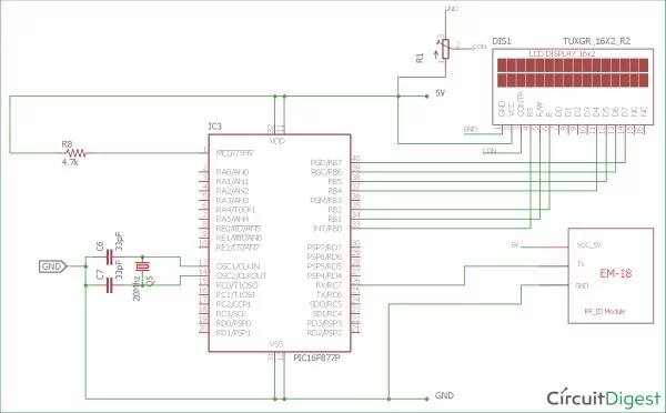
The schematic is simple; we connected LCD across port RB and connected the EM-18 module across the UART Rx pin.
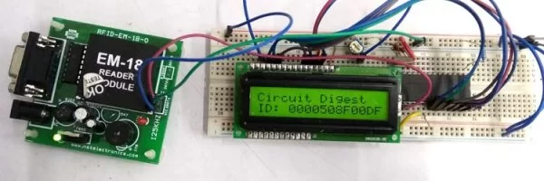
We have made the connection on breadboard according to schematic.
Code Explanation
As always, first we need to set the configuration bits in the pic microcontroller, define some macros, including libraries and crystal frequency. You can check code for all those in the complete code given at the end.
// PIC16F877A Configuration Bit Settings
// 'C' source line config statements
// CONFIG

#pragma config FOSC = HS        // Oscillator Selection bits (HS oscillator)
#pragma config WDTE = OFF       // Watchdog Timer Enable bit (WDT disabled)
#pragma config PWRTE = OFF      // Power-up Timer Enable bit (PWRT disabled)
#pragma config BOREN = ON       // Brown-out Reset Enable bit (BOR enabled)
#pragma config LVP = OFF         // Low-Voltage (Single-Supply) In-Circuit Serial Programming Enable bit (RB3/PGM pin has PGM function; low-voltage programming enabled)
#pragma config CPD = OFF        // Data EEPROM Memory Code Protection bit (Data EEPROM code protection off)
#pragma config WRT = OFF        // Flash Program Memory Write Enable bits (Write protection off; all program memory may be written to by EECON control)
#pragma config CP = OFF         // Flash Program Memory Code Protection bit (Code protection off)

#include "supporing_cfile\lcd.h"
#include "supporing_cfile\eusart1.h"
If we see the main function we called a function to initialize the system. We initialize LCD and UART in this function.
/*
 This Function is for system initializations.
 */

void system_init(void){
    TRISB = 0x00; //PORT B set as output pin
    lcd_init(); // This will initialize the lcd
    EUSART1_Initialize(); // This will initialize the Eusart
}
Now, in the main function, we used a 13 bit array which is RFID Number. We receive each bit of the RFID no. using EUSART1_Read(); function, which is declared inside of the UART library. After receiving 12bits, we print the Array as string in the LCD.
void main(void) {
    unsigned char count;
    unsigned char RF_ID[13];
    system_init();
    lcd_com(0x80);
    lcd_puts("Circuit Digest");
    while (1){
        for (count=0; count<12; count++){
            RF_ID[count] = 0;
            RF_ID[count]=EUSART1_Read();
        }
        lcd_com(0xC0); // Set the cursor for second line beginning
        lcd_puts("ID: ");
        lcd_puts(RF_ID);
    }
}
/*
* File: main.c
* Author: Sourav Gupta
* By:- circuitdigest.com
* Created on August 15, 2018, 2:26 PM
*/
// PIC16F877A Configuration Bit Settings
// ‘C’ source line config statements
// CONFIG
#pragma config FOSC = HS // Oscillator Selection bits (HS oscillator)
#pragma config WDTE = OFF // Watchdog Timer Enable bit (WDT disabled)
#pragma config PWRTE = OFF // Power-up Timer Enable bit (PWRT disabled)
#pragma config BOREN = ON // Brown-out Reset Enable bit (BOR enabled)
#pragma config LVP = OFF // Low-Voltage (Single-Supply) In-Circuit Serial Programming Enable bit (RB3/PGM pin has PGM function; low-voltage programming enabled)
#pragma config CPD = OFF // Data EEPROM Memory Code Protection bit (Data EEPROM code protection off)
#pragma config WRT = OFF // Flash Program Memory Write Enable bits (Write protection off; all program memory may be written to by EECON control)
#pragma config CP = OFF // Flash Program Memory Code Protection bit (Code protection off)
#include <xc.h>
#include <stdio.h>
#include <string.h>
#include “supporing_cfile\lcd.h”
#include “supporing_cfile\eusart1.h”
/*
Hardware related definition
*/
#define _XTAL_FREQ 200000000 //Crystal Frequency, used in delay
/*
Other Specific definition
*/
void system_init(void); // This will initialize the system.
void main(void) {
unsigned char count;
unsigned char RF_ID[13];
system_init();
lcd_com(0x80);
lcd_puts(“Circuit Digest”);
while (1){
for (count=0; count<12; count++){
RF_ID[count] = 0;
RF_ID[count]=EUSART1_Read();
}
lcd_com(0xC0); // Set the cursor for second line begining
lcd_puts(“ID: “);
lcd_puts(RF_ID);
}
}
/*
This Function is for system initializations.
*/
void system_init(void){
TRISB = 0x00; //PORT B set as output pin
lcd_init(); // This will initialize the lcd
EUSART1_Initialize(); // This will initialize the Eusart
}
Read more Detail:RFID Interfacing with PIC Microcontroller
- What is the primary function of the RFID module described?
The module reads or writes small amounts of data into Passive RFID tags for identification processes. - Which microcontroller is used to interface with the RFID module?
The project uses the PIC Microcontroller PIC16F877A. - How does the EM-18 module communicate with the microcontroller?
The module uses the UART communication protocol at a 9600 Baud rate. - What logic level does the output of the EM-18 reader use?
The output of the EM-18 reader uses 5V logic level. - How many bits constitute the RFID tag number in the UART output?
The first 10 bits are the RFID tag number, while the last two digits are for error testing. - What type of RFID tags are utilized in this specific project?
The project uses 125Khz Passive RFID cards that hold unique ID data. - What happens when a valid frequency tag enters the magnetic field?
The BC557 transistor turns on, causing the buzzer to beep and the LED to glow. - Can a 3.3V microcontroller be used without extra components?
In some cases, the UART pin of a 3.3V microcontroller is 5V tolerant, but a logic level converter might be required otherwise.