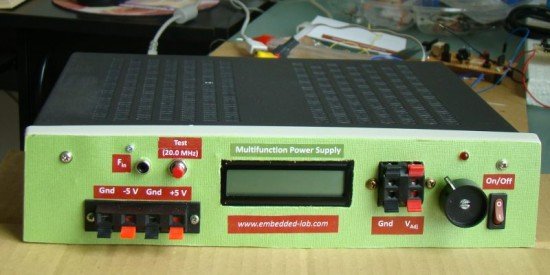
One important parameter in embedded system designing is power consumption. This parameter is directly related to the battery lifetime, if the system is to be powered from a battery. In order to determine the power rating of your designed system, you need to know how much current the system draws from the source at a given voltage. While working on my projects, I usually measure current by placing an external ammeter in series with the current’s return path. This is not always convenient to do, and so I thought of making a special power supply unit for my lab that would display both voltage and current information on a LCD screen while prototyping my circuit. This way I can continuously monitor how much power my test circuit is drawing at a specific operating voltage.

This power supply unit provides fixed ±5 V as well as a variable dc voltage ranging from 1.25 V to 9 V. A PIC16F689 microcontroller is embedded into the power supply unit to measure the adjustable output voltage along with the load current. Besides, this unit also has a built-in frequency counter to measure the frequency of an external signal. The range is over 50 MHz. However, it has been tested up to 20.0 MHz, and works fine. There are still few I/O ports of PIC16F689 that are not used. So I am thinking about adding one or more features (like capacitance meter) to it. But that would be on my second version.
Theory
The fixed ±5 V power supplies are derived using LM7805 and LM7905 regulator ICs. A 12 V rectified output from a center-tapped transformer provides the dc inputs to these regulator ICs. For the variable dc output, a LM350 IC is used. LM350 is an adjustable 3-terminal positive voltage regulator that is capable of supplying in excess of 3A over a 1.2V to 33V output range. It requires only 2 external resistors to set the output voltage. Since my dc input is only 12 V (rectified output from the transformer), the regulated output from the LM350 IC would go up to 9 V (3 V less than the input, as specified in the datasheet). In order to obtain the full range of output voltage (up to 33 V) from LM350, you need a transformer with a higher output voltage. I rarely use power supply above 5 V in my projects, and therefore, a variable voltage source up to 9 V is good enough for me.
Next comes PIC16F689 microcontroller that measures the LM350 output voltage and current. You are right, I am implementing voltage and current measurement only to the LM350 output. The principles of voltage and current measurements using microcontroller were discussed in two of my posts: PIC-based digital voltmeter and How to measure dc current with a microcontroller. I am not going to repeat the details here. Both the parameters can be measured with built-in ADC channels of PIC16F689. Since the output voltage from LM350 could go higher than 5 V (up to 9 V in this situation), it is not directly measurable from an ADC channel. A simple voltage divider network using two resistors is incorporated to scale down the output voltage to the safe ADC input range (0-5 V). On the other hand, the current to be measured must be first converted into voltage so that it could me measureable too with the ADC channels. The current to voltage conversion can be done by placing a small value resistance (shunt) in series with the current path. The voltage drop across the resistance will then vary linearly with the current. I am using a 0.286 ? resistor (Rs) made by myself by coiling a 5 ft long 22 AWG solid copper wire that has a plastic insulation on its outer surface (see the picture below).

Since this resistance is so small in value, the voltage drop across won’t be very high for small currents. Even for 1 A of current, the voltage drop across it would be only 0.286 V. To improve the resolution (and hence accuracy) of current measurement, this voltage must be amplified before the AD conversion process. An operational amplifier with a suitable gain can do this task. The figure below shows how this whole technique works.
For more detail: A new multi-function power supply unit for my Embedded Lab
