


Summary of LED UV exposure box
This article details the construction of a compact UV LED exposure box for PCB fabrication, replacing an older UV tube setup. The author optimized LED spacing and distance to achieve uniform density while ensuring safety and professional features like automatic light control upon opening the box.Parts used in the DIY UV LED Exposure Box:
- OSSV53E1A UV LEDs (25 units)
- 91Ω resistors
- LM317 voltage regulator
- Red alignment LEDs
- 220Ω resistors
- 330Ω resistor
- On/Off switch with magnetic sensor
- Timer mechanism
- 12V power supply
Introduction
I have been using the toner transfer method for about 9 years with great results. Occasionally I would need a board with finer traces and I would use UV method. My exposure setup allowed only a single sided board to be made and it was composed of a 30cm UV tube, some holders, a table, board and film. Exposure time was rather long as the tube was far away from the board.
A few months ago I was looking for some LEDs at one of my suppliers and found that the also had UV LEDs. My mind went directly to upgrading my not so great setup, so I began looking on the internet for info. It turns out some other people have done it, and this instructable confirmed it was really possible. A LED UV box has a clear advantage over a tube one: it can be made in any size, depending on the needs.
I bought 25 LEDs and began to experiment. This way I was able to find a compromise between LED density (spacing), distance between LEDs and board and cost. I wanted something compact, I don’t make large PCBs and those 30cm tubes were not right for this job.
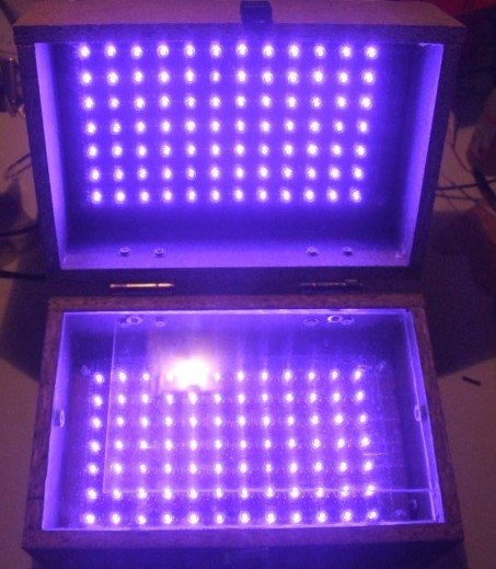
Note: Don’t look directly into the UV LEDs. It harms your eyes.
The LEDs
The LEDs are OSSV53E1A from OptoSupply and they have an 140° angle. This means that the first plane with uniform density can be obtained at a shorter distance from the LED, for a given spacing between LEDs which means smaller height for the board. Their peak wavelength is 405nm, which is higher than recommended by the boards’ manufacturer. Results showed they emit sufficient UV light in the responsive spectrum of the photo resist to allow for a perfect exposure.
I wanted to use a common voltage so 3 LEDs in series with a 91Ω resistor are connected to 12V to ensure a 20mA current.
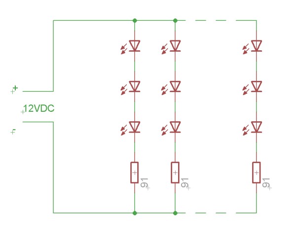
The final setup will contain a LM317 for stabilizing as I don’t plan on using my variable regulated supply all the time. There is another reason for this, due to the non linear nature of the LEDs, varying 12V with +/-5% creates much larger current variations which influences the required time. Putting a regulator on the box simply allows more flexibility in choosing the power supply.
On the bottom board I have added red LEDs. These LEDs help me align the top and bottom films. I have used low brightness, cheap, matte LEDs as I have to look into them when aligning the films. Connection is similar, 3 LEDs in series with a 220Ω resistor, except for the last row which contains 2 LEDs and a 330Ω resistor. These are not really necessary, aligning the films can be done in a dim ambient light.
For safety reasons and extra functionality I added a switch to turn off the UV light when the box opens, turn on the red light and stop the timer. This makes the box more high tech and gives it a professional behavior.
For more detail: LED UV exposure box
Quick Solutions to Questions related to DIY UV LED Exposure Box:
- Why did the author upgrade from a UV tube setup?
The new LED box is compact, can be made in any size, and offers better performance for small PCBs compared to the 30cm tube. - What are the specifications of the UV LEDs used?
The project uses OSSV53E1A LEDs with a 140° angle and a peak wavelength of 405nm. - How are the UV LEDs connected electrically?
Three LEDs are connected in series with a 91Ω resistor to 12V to ensure a 20mA current. - Why is an LM317 regulator included in the design?
The regulator stabilizes the current because varying voltage creates large current variations due to the non-linear nature of the LEDs. - What is the purpose of the red LEDs on the bottom board?
They help align the top and bottom films during the exposure process. - How does the safety switch function when the box opens?
It turns off the UV light, turns on the red alignment lights, and stops the timer. - Is it safe to look directly into the UV LEDs?
No, looking directly into the UV LEDs harms your eyes. - Can the films be aligned without the red LEDs?
Yes, aligning the films can be done in dim ambient light as the red LEDs are not strictly necessary.
Related projects
An Application-Driven Microcontroller Curriculum
Understanding how to apply microcontrollers lies at the core of modern embedded systems education. This student project takes an experiential approach to...
LED ProjectsBuild this microcontroller controlled rainbow flying disc – and then throw it!
Hello all and welcome to this super simple and inexpensive instructable. If you like throwing frisbees AND you like flashing lights AND...
LED ProjectsLED Scrolling Display Project Working With Circuit Diagram
We normally use a simple static LED display screen to convey a message. Earlier, when we want to display large data, we...
LED Projects8051 MICROCONTROLLER
8051 Microcontroller based electronic locker system CIRCUIT DESCRIPTION Security is a prime concern in our day-today life. Everyone wants to be as...
LED ProjectsDigital Temperature Sensor Circuit
Temperature sensors are widely used in electronic equipments to display the temperature. You can see the digital clock displaying the room temperature...
LED ProjectsPassword Based Door Lock System using 8051 Microcontroller
Traditional lock systems using mechanical lock and key mechanism are being replaced by new advanced techniques of locking system. These techniques are...

Ibrar Ayyub
I am an experienced technical writer holding a Master's degree in computer science from BZU Multan, Pakistan University. With a background spanning various industries, particularly in home automation and engineering, I have honed my skills in crafting clear and concise content. Proficient in leveraging infographics and diagrams, I strive to simplify complex concepts for readers. My strength lies in thorough...