Summary of How to interface LCD with PIC18F4550 Microcontroller
This article details interfacing a 16x2 character LCD with a PIC18F4550 microcontroller to display alphanumeric characters. The LCD operates in 8-bit mode, connecting data pins D0-D7 to PortB and control pins (RS, R/W, EN) to PortA. The project includes initialization steps, command/data transmission logic, and C source code demonstrating how to print specific characters like 'E' and 'G'.
Parts used in the LCD Interfacing Project:
- LCD
- PIC18F4550
- Preset
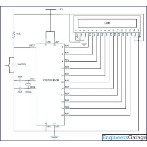
The character LCDs are the most commonly used display modules. These LCDs are used to display text using alphanumeric and special characters of font 5×7/5×10. For basic working and operations of a character LCD, refer LCD interfacing with 8051. Here PIC18F4550 has been used to display a single character on a 16×2 character LCD.
For basic details and operations of character LCD, refer LCD interfacing with 8051. Here LCD has been interfaced in 8-bit mode* with data pins (D0-D7) connected to PortB of PIC18F4550. The LCD control pins RS, R/W and EN are connected to PortA pins RA0, RA1 and RA2 respectively.
Project Source Code
###
// Program to interface 16×2 LCD and display single character using PIC18F4550 Microcontroller
// Configuration bits
/* _CPUDIV_OSC1_PLL2_1L, // Divide clock by 2
_FOSC_HS_1H, // Select High Speed (HS) oscillator
_WDT_OFF_2H, // Watchdog Timer off
MCLRE_ON_3H // Master Clear on
*/
//LCD Control pins
#define rs LATA.F0
#define rw LATA.F1
#define en LATA.F2
//LCD Data pins
#define lcdport LATB
void lcd_ini();
void lcdcmd(unsigned char);
void lcddata(unsigned char);
unsigned int i=0;
void main(void)
{
TRISA=0; // Configure Port A as output port
LATA=0;
TRISB=0; // Configure Port B as output port
LATB=0;
lcd_ini(); // LCD initialization
lcddata(‘E’); // Print ‘E’
Delay_ms(1000);
lcdcmd(0x85); // Position 1st Line, 6th Column
lcddata(‘G’); // Print ‘G’
}
void lcd_ini()
{
lcdcmd(0x38); // Configure the LCD in 8-bit mode, 2 line and 5×7 font
lcdcmd(0x0C); // Display On and Cursor Off
lcdcmd(0x01); // Clear display screen
lcdcmd(0x06); // Increment cursor
lcdcmd(0x80); // Set cursor position to 1st line, 1st column
}
void lcdcmd(unsigned char cmdout)
{
lcdport=cmdout; //Send command to lcdport=PORTB
rs=0;
rw=0;
en=1;
Delay_ms(10);
en=0;
}
void lcddata(unsigned char dataout)
{
lcdport=dataout; //Send data to lcdport=PORTB
rs=1;
rw=0;
en=1;
Delay_ms(10);
en=0;
}
###
Circuit Diagrams
Project Components
Project Video
Source: How to interface LCD with PIC18F4550 Microcontroller
- How is the LCD configured for operation?
The LCD is configured using commands like 0x38 for 2-line, 5x7 font, and 8-bit mode. - Can the LCD be interfaced in 4-bit mode?
Yes, the text states that Character LCD can also be interfaced by using only 4 data lines. - Which ports connect to the LCD data pins?
Data pins D0 through D7 are connected to PortB of the PIC18F4550. - What is the function of the RS pin?
RS selects the register; it is set to 0 for command registers and 1 for data registers. - How does the system clear the display screen?
The system sends the command byte 0x01 to clear the display screen. - Does the project use an internal oscillator?
No, the configuration bits select a High Speed (HS) oscillator. - What happens when EN is pulsed high to low?
A high to low pulse on EN latches the command instruction or data into the LCD. - How is the cursor positioned initially?
The cursor position is set to the first block of the first line using command 0x80.