Summary of How to create custom characters on 16×2 LCD using PIC18F4550
This article explains how to display custom characters like hearts and smileys on a 16x2 LCD using a PIC18F4550 microcontroller. It details generating bitmaps via the mikroC IDE, storing them in CGRAM, and utilizing a specific C function to render these shapes. The guide covers hardware setup, programming logic for bitmap transmission, and provides complete source code for implementation.
Parts used in the Custom Characters on 16x2 LCD Project:
- 16x2 Character LCD
- PIC18F4550 Microcontroller
- Preset (Variable Resistor)
- mikroC IDE Software
The 16×2 character LCD can also be used to display custom characters other than numerals, alphabets & special characters. Refer LCD interfacing with PIC. Some special shapes like hearts, arrows, smileys etc. can easily be displayed on the 5×8 pixel pattern of character LCD. These shapes are first stored at a special location in LCD’s controller and then displayed on the LCD module. This procedure has been explained here by using PIC18F4550.
The special characters are generated by bit-mapping of LCD’s 5×8 bit pixel matrix. Refer Creating custom characters on LCD using 8051 for more details on bitmap generation and storing custom values in custom generator (CG) RAM of LCD’s controller.
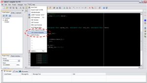
The mikroC IDE provides LCD Custom Character tool to create the bitmap of user defined custom character. (Also see Working with mikroC) To create the bitmaps using this tool, following steps are to be followed:
1. Go to Tools -> LCD Custom Character
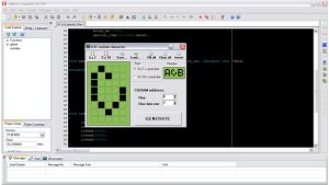
2. Select 5×7 + cursor line font and start filling the pixels in the matrix by clicking on them to create a custom character. The following figure depicts the generation of heart shape’s bitmap.
3. After creating the character and click on GENERATE button. A window will appear containing the bitmap values of designed custom character as highlighted in the following figure.
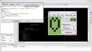
4. These bitmap values can now be used in the code.
|
ASCII Code
|
Base Address
|
|
0
|
64
|
|
1
|
72
|
|
2
|
80
|
|
3
|
88
|
|
4
|
96
|
|
5
|
104
|
|
6
|
112
|
|
7
|
120
|
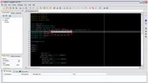
Project Source Code
###
// Program to display custom characters on 16×2 LCD using PIC18F4550 Microcontroller
// Configuration bits
/* _CPUDIV_OSC1_PLL2_1L, // Divide clock by 2
_FOSC_HS_1H, // Select High Speed (HS) oscillator
_WDT_OFF_2H, // Watchdog Timer off
MCLRE_ON_3H // Master Clear on
*/
//LCD Control pins
#define rs LATA.F0
#define rw LATA.F1
#define en LATA.F2
//LCD Data pins
#define lcdport LATB
void lcd_ini();
void lcdcmd(unsigned char);
void lcddata(unsigned char);
void special_char(unsigned char, unsigned char, unsigned char *);
unsigned char data1[]={10,21,17,17,17,10,4,0}; // Bitmap values of “heart” shape
unsigned char data2[]={12,18,1,2,4,8,0,8};
unsigned char data3[]={1,3,5,9,9,11,27,24};
unsigned int i=0;
void main(void)
{
TRISA=0; // Configure Port A as output port
LATA=0;
TRISB=0; // Configure Port B as output port
LATB=0;
lcd_ini(); // LCD initialization
special_char(64,0×82,data1); // Function call to store “Heart” shape’s bitmap at 64th base address
// and print it at 0x82 location on LCD
Delay_ms(1000);
special_char(72,0×84,data2);
Delay_ms(1000);
special_char(80,0×86,data3);
}
void special_char(unsigned char cgram_loc, unsigned char lcd_loc, unsigned char *data)
{
unsigned int j=0;
lcdcmd(cgram_loc); // Send location of CGRAM
while(j<8)
{
lcddata(data[j]); // Send bitmap values of the character
j++;
}
lcdcmd(lcd_loc); // Send LCD location where the character is to displayed
lcddata((cgram_loc-64)/8); // ASCII value of corresponding base address
}
void lcd_ini()
{
lcdcmd(0x38); // Configure the LCD in 8-bit mode, 2 line and 5×7 font
lcdcmd(0x0C); // Display On and Cursor Off
lcdcmd(0x01); // Clear display screen
lcdcmd(0x06); // Increment cursor
lcdcmd(0x80); // Set cursor position to 1st line, 1st column
}
void lcdcmd(unsigned char cmdout)
{
lcdport=cmdout; //Send command to lcdport=PORTB
rs=0;
rw=0;
en=1;
Delay_ms(10);
en=0;
}
void lcddata(unsigned char dataout)
{
lcdport=dataout; //Send data to lcdport=PORTB
rs=1;
rw=0;
en=1;
Delay_ms(10);
en=0;
}
###
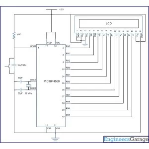
Circuit Diagrams
Project Components
Project Video
Source: How to create custom characters on 16×2 LCD using PIC18F4550
- How can special shapes be displayed on a 5x8 pixel matrix?
Special shapes are created by bit-mapping the pixel matrix, storing the resulting values in the LCD controller's CGRAM, and then displaying them. - What tool does mikroC IDE provide to create custom character bitmaps?
The mikroC IDE provides an LCD Custom Character tool found under Tools > LCD Custom Character to generate user-defined bitmaps. - How many custom character bitmaps can the CGRAM store?
The CGRAM of the LCD controller module can store up to eight custom character bitmaps. - What is the base address for the first custom character in CGRAM?
The base address for the first custom character (ASCII Code 0) is 64. - How are bitmap values sent to the LCD controller?
After selecting the base address as a command instruction with RS=0, bitmap values are sent one by one as data with RS=1. - What determines the ASCII value printed for a stored custom character?
The ASCII value is calculated based on the base address of the CGRAM using the formula (cgram_loc-64)/8. - Which microcontroller is used in this project example?
The project uses the PIC18F4550 microcontroller to control the LCD display. - Can numerals and alphabets be replaced with custom shapes?
Yes, the 16x2 character LCD can display custom characters other than standard numerals, alphabets, and special characters.