Introduction
Our team being excited by the recent trend towards more active forms of entertainment, such as those provided by motion-control systems and virtual-reality headsets, set out to create a similar type of device. We were further inspired by the games Rhythm Heaven and Dance Dance Revolution, in which the different physical inputs made by the player worked to create a rhythm that the player essentially danced to. Thus, we formulated Groovy Times, a game in which the player is prompted by on-screen directions to move to a beat that their performance impacts the sound of. We made use of the PIC32 microcontroller, an MMA8451Q accelerometer, and two RF69HCW radios (connected through Arduino) to implement a fully untethered game that gets the player groovin’ on their feet.
High Level Design
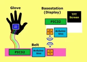
The goal of this game was to emulate the simple mechanics of games like Dance Dance Revolution and Rhythm Heaven: pattern matching with movements. Dance Dance revolution used steps on a mat, while Rhythm Heaven used flicks and taps of a stylus. We aimed to use the positions of a person’s hands as elements in the patterns. The exact way the game functions is that an arrow would appear on the screen, and the player would tilt the glove wearing hand towards that direction. Upon reaching the correct location within the given time frame, the player would get a point and proceed to the next arrow on screen. After a certain period of time, the game would move forward even if the player did not reach the specific hand direction, and the player would not get points for the motion. This meant we needed to allow the player to be completely mobile in our hardware so that actively moving would be a fun aspect of the game. The meant we needed wireless communication between the interface calculating the player’s position and the interface displaying the game. These two interfaces were separated into the “belt” and the “basestation”. Currently the trademarks related to the game are the previously mentioned games. However, we our implementation was only differed significantly from these potential implementations, so this was not a large concern. We selected this project because all of the group member found a game where we used a physical interaction to transfer into a digital realm. We additionally found the task of integrating all of the components together both daunting and exciting.
The main obstacle we had to overcome, in this regard, was how and what we were going to send to the base station from the belt. Our form of communication was RF radios, controlled by Arduinos over SPI, one at each of the separate interfaces. The belt Arduino would take information from another microcontroller, the PIC32, which calculated a player’s hand position. From here, we did not want the packets of information to be too complicated so that if a piece of data was lost, the state of the game would not be severely corrupted. Therefore, the belt Arduino radio sent simple encoded “states” to the base station. Each state was an integer that represented “UP”, “DOWN”, “LEFT”, “RIGHT”, or “NONE”. Also, to comply with FCC standards, we set our radio’s encoding frequency to be 915MHz, even though our radio’s could be set up to be below the legal frequency limit. We did not have any other concerns regarding other standards.
The base station radio would receive these positional state packets and check the user’s position against the state displayed on the screen. If they matched, the player was awarded a point. At the end of a level, the player has their overall score displayed and they are prompted to play again, and even select another level.
A key hardware to software trade off was the decision to use Arduinos in our design. Although the Arduino added a significant amount of hardware, we decide that this addition would be worth it to make up for the availability of a library which interfaced with the RF modules we selected. Additionally, we focused on making the game completely wireless so that the person playing the game could have a full range of motion.
Program Design
Main Game
Groovy Times is organized into three game states – Start Menu, Song Select, and Gameplay. Each game state is allocated its own thread, which is scheduled only if the game_state variable is set to: 1 for Start Menu, 2 for Song Select, and 3 for Gameplay as shown in Figure 2. Along with these, two other threads are continuously scheduled regardless of game_state — the Input Controller and Sound Controller. Code for setting up essential game elements and scheduling threads is also included in the song_test.h and songdefs.h headers, as well as the main() method.
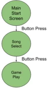
Main
The main() method begins by setting up the array of all songs, aptly named “songs”. This array is filled by pointers to all of the songs instantiated in the <b>song_test.h</b> header. It follows this by setting up all of the registers and calling all of the appropriate methods necessary to set up and enable the ADC on pin AN11 with no auto sampling. It then instantiates 4 sine tables of widths 256, 128, 64, and 32, that will be used to playback sound effects throughout the game. Next SPI channel 2 is setup for the DAC unit. As the DAC is going to be operated via DMA, we require enabling OpenTimer2 to setup the DMA channel. DMA channel 0 is then opened and set into auto mode -e effectively concluding setup of the DMA and DAC. Following this, the methods for setting up the TFT are called (tft_init_hw(), tft_begin()). As we’d like our entire game to be played with the TFT set horizontally, we also call tft_setRotation(1), which flips the axes (long side is x-axis, short side is y-axis). Lastly, protothreads, along with the 5 aforementioned threads are initialized and interrupts are enabled. At this point, main() purely becomes a round-robin scheduler that constantly schedules the Input Controller Thread and Sound Controller thread, and schedules one of each of the game state threads depending on the value of the game_state variable (for example, if game_state is equal to 2, the Song Select thread is scheduled only).
songdefs.h
This header file only contains two type definitions and macros to define each direction (LEFT, UP, RIGHT DOWN, NONE) as a char. The type definitions define a “movez” and a “song”.
Movez are collections of two directions (defined as chars as above), and two integers named “time” and “delay”. The two direction chars represent the two directions that the player needs to move their left and right hands respectively. Note that although the final implementation of the game, only one direction is displayed due to limited resources, but the program supports an addition of a second direction should this ever be expanded. The char direction is encoded according to the macros defined above. The “time” integer represents how long in milliseconds a single move should stay on screen for before checking whether or not the player ever hit the move properly. Lastly, the “post_move_delay” integer determines how long (in milliseconds) after the previous move has been checked (i.e. after the “time” has run out) the game should wait before moving on to the next move. The purpose of varying these last two integers is in allowing the moves and checks, both which produce some sound upon occuring, to have variable time in between them. Doing so essentially allows the programmer to compose a tune out of the game sounds that the user dances to – much like our inspiration game, Rhythm Heaven.
An instance of type “song” consists of a character pointer (i.e a string) which represents the name of the song, and a pointer to a movez instance, denoted m. The pointer to the movez instance is intended to be instantiated by an array of movez. This collection of movez represents the entire song that will be grooved to for a single level. Thus, a song instance can be considered a level of the game.
song_test.h
Song_test.h is where all levels (i.e. songs) and their corresponding movez arrays are instantiated. We developed 4 songs in our code to demonstrate varying song lengths, move lengths (“time” field), and move transition lengths (“post_move_delay” field). Each movez array declaration, (and the movez themselves) is prepended with the “static const” keywords, which directs the compiler to store this array and its components in flash memory. This decision allows for many more songs of potentially very-large lengths to be added to the game if desired, as they will not occupy the limited program memory. Each movez array concludes with a special move, with all fields equal to -1. This is so the main program can check is the array, and by extension the song, has concluded.
Input Controller Thread
The Input Controller thread is the connection between all off-board actions(except sound) and the game. It abstracts all of the various inputs from the game and threads, and instead polls for all player interaction at a high frequency (50ms). Only the inputs that are necessary for the current game state are polled for — the value they take on being saved into global variables that can then be used by the threads for the given game state. The Input Controller also sets up RPA4, RPB3, RPB4, RPB7, RPB8, RPB9, and RPB13 as digital inputs and sets the internal pull-downs for all of them except RPB13.
When the game is in the Start Menu game state, this thread only polls for a reading on RPB7. RPB7 is externally connected a button – the only one the player may interact with on the base. When this reads a value, the menu_button global is set to 1, which may then be used by the Start Menu thread. Similarly, when the game state is set to Song Select, the Input Controller polls the RPB7 button to set the song_select global. This state also makes use of the ADC which is externally attached to a potentiometer through the circuit shown in figure 12 in the Appendix.
As such, the Input Controller makes a reading of the ADC. This reading ranges from 0-1023, however, and needs to be scaled to a value usable by the Song Selection thread. It is first multiplied by the total amount of songs, then divided by the ADC range (executed by a 10 bit right shift) to give an index between 0-MAX_SONGS for a given ADC reading. This value is saved in the song_slide global, which is accessed by the Song Select thread. The Gameplay state takes the most inputs in this thread. It first checks for input in the same RPB7 connected button. The button here is “debounced” by polling for the button, which sets the “buttstate” field, then polling for a release of the button once this field is set. After this, the reset global is set, which is used by the Gameplay thread. Next, input is taken from RPB3, RPB4, RPA4, RPB9, and RPB8. These 5 pins are connected to the Arduino’s digital out pins, which transfer in data from the accelerometer readings, though only the directions(LEFT, UP, RIGHT, DOWN, NONE) that the accelerometers in each hand are in is transferred over.When these 5 inputs have their logical values concatenated (in the order listed), they form a 5-bit field denoted game_input. This value is the encoded state of the accelerometers (encoded to fit into 5 bits), which is decoded by the Input Controller next. The decoder is implemented as a switch-case structure, simply taking the value of game_input and converting it straight to an instantiation of the globals keeping track of the player’s accelerometer state. These global variables are named port_state and star_state (for port and starboard) for the left and right hands respectively. This part of the input controller also writes the state of left and right hands to the bottom center of the screen. Note that the current version of the game only does this for one hand (the port hand), although the support for both hands exists and can be turned on at any time.
Sound Controller Thread
This thread controls all sound output from the PIC32. It instantly yields until one of the flags it is sensitive to is set. Each of these flags, score_flag, miss_flag, clap_flag, and boop_flag, triggers the output of a different sine table to the speakers for ~1 second, allowing sound effects of different pitch to be emitted. All sound is sent to the DAC via DMA. Upon any flag being set, the DMA channel is first disabled so we may configure. We write 0x00 to to the PIC32’S Timer 3, then call DmaChnSetTxfer() to set up the flag’s respective sine table as the DMA’s output. The flag is also reset.We then enable the DMA channel with DmaChnEnable() and yield the thread for 5 milliseconds at a time, repeatedly checking Timer 3 to see if ~1 second has passed (50000 ticks). Once it has, the DMA channel is again disabled, and the thread reset, then yielded until another flag is set.
Start Menu Thread
This thread controls the very first thing a user sees upon startup. It simply writes the title of the game onto the TFT and toggles the visibility of the “Press Start” text every 700ms. It also checks whether or not the menu button has been pressed in the last 700ms by checking the menu_button field. Upon this, it will change the game_state to “select” and stop the scheduler from scheduling itself anymore. This transition also temporarily sets the “boop_flag”, which communicates to the Sound Controller that it should play the “boop” sound effect (more on this in Sound Controller section).
Song Select Thread
The Song Select thread is in charge of setting up the game elements for actual gameplay. During this game state, the user takes control of the knob (potentiometer) attached to the big board, which controls the variable song_slide (more discussed in Input Controller section). The value of song_slide determines which song is being selected by serving as an index to the songs array put together in main(). The title of the selected song in taken and written to the center of the screen in size 3 text – indicating to the user that this is their selection. Two songs ahead and two songs behind of the selection are displayed below and above the selection in smaller text to give the effect of a selection dial for this entire screen. In order to prevent any noticeable screen flickering, the screen is only completely redrawn when the value of song_slide changes. Changing the value of song_sliide also activates the boop-flag for a side effect.
A field called song_select is set by the button connected to the white board (elaborated on in Input Controller). This field being read as logical high will select the song currently highlighted as the “playing song”, and load the next level, based on its data,for gameplay. The player is greeted with a message saying “GET READY TO GROOVE TO” followed by the title of their selected tune. This gives them a second to get ready for gameplay. At this point, the game state is changed to Gameplay and the thread is descheduled.
Gameplay Thread
A player is expected to spend the most time in the Gameplay thread, as this is where all actual gameplay logic is implemented. Standard gameplay works as follows: the player is prompted with 2 arrows (in this version just one) denoting the direction(s) they should move arm(s). Using the printed out player input (mentioned in the Input Controller section) as feedback, they try to match the arrow(s) with their arms. After a predetermined amount of time, their input is checked, and if good the player will be shown a verifying graphic (a green circle), or if bad shown an appropriate graphic for that (a red X). The next move is then shown after a time dependent on the song.
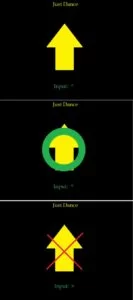
The first thing the thread does is output the title of the song at the top of the screen constantly, just to serve as a reminder which level is being played. Next, the player input is checked provided that this is not the first move, as otherwise there would be no move to check at all. The expected move direction (LEFT, UP, RIGHT, DOWN) is directly compared to the states of the player’s inputs (port_state and star_state, as discussed in Input Controller) to determine if the player scored or not. If they do, their score is incremented, a thick green circle is drawn on the screen, and the score flag is set. Otherwise,the score is unaffected, a red X is drawn to screen, and the miss flag is set. The setting of one of these flags will schedule the Sound Controller to play either a high pitch sound for a score, or low pitch sound for a miss. Following this check stage, the thread is yielded for “post_move_delay” milliseconds – allowing for song composition as discussed in the songdefs.h section. The screen is then cleared to allow the next move to be drawn. Before that next move is displayed, however, we must check that the previous move was not the final one. This is done by checking for a special endflag value that every movez array concludes in (-1). Should this state be entered, the player’s total score is drawn on screen — presented as a fraction of their successful moves over the total amount of moves. All utilized global fields are then reset, and the game hangs until the reset flag is set (done by Input Controller). This transitions the game back to the Song Select state, where a user may choose the next song they want to groove to. Should the endflag value not be present, however, the next move is read. An integer named movez_iter constantly keeps track of the current move being done. It is used here to access the proper port (left hand) and star(right hand) move from the song’s movez array — along with the proper time and post_move_delay for it. These values are stored in local variables, so that the movez array does not have to be continually accessed to use them. Following that, the movez (or in this implementation, just the port move) get drawn to the screen as arrows by utilizing the move2screenPORT() and move2screenSTAR() helper functions. The clap_flag is also set, once again yielding to the Sound Controller. This time it plays a “mid-pitch” sound, meant to serve as a “clap” that complements the sound made by the player’s input action. The movez_iter counter is then incremented, and the thread is yielded for the amount of time that the current move demands (from its “time” field).
Small Board on Body PIC
The interface with the accelerometer utilized the PIC32’s given I2C functionalities. We used a slightly modified version of I2C implementation a previous design project: Blimp-O (http://people.ece.cornell.edu/land/courses/ece4760/FinalProjects/f2015/bjr96_jl2628/bjr96_jl2628/bjr96_jl2628/index.html). In main, we set up a few start up registers to configure the program. This was useful for debugging, because if no threads were scheduled, we knew that the I2C protocol was being stuck in the main function. Then, in a defined function getDataPort(axis), we used the I2C protocol for reading data from the accelerometer at the register axis, defined at the function call. In other words, whatever register value we put into getDataPort, we would read from the accelerometer. The most significant bytes of the x,y,z data outputs were 0x01, 0x03, and 0x05. We used these values to get a number between 64 and -64, which defined the state of each axis. Specifically, we created an I2C thread to call the function three times to receive all three axises at once and set them into global variables xAccelPort, yAccelPort, and zAccelPort.
These global variables would then be passed into another thread called direction. This thread would determine what direction the accelerometer was facing based on the current values of the accelerometer. Each direction had set parameters that defined each axis value in that position. In order to be defined as a certain direction, the current values had to be in a certain threshold of the set parameters. This threshold was set to 30 on either side of the set parameter. For example, if the x axis had to be -40 to be considered “UP”, in reality, they had to be either -10 or -64 (theoretically -70, but the accelerometer did not have that range). This set threshold had to be met for all three axes. Once a direction was set (either UP, DOWN, LEFT, RIGHT or NONE), three output pins were set or cleared, depending on the predetermined numbering standard. A high pin meant a logic bit 1 and a low pin meant a logic bit 0. These high and low values were read by the Arduino in the following scheme:
UP = 000
DOWN = 001
LEFT = 010
RIGHT = 011
NONE = 100
Another feature on the belt was the calibration mode. In the case where a player felt the predetermined values and ranges of the different direction states were not accurate to their motions, they could start a calibration sequence. When a button was pushed on the belt, it set a flag in the direction thread that descheduled the direction thread and would schedule the calibrate thread. The calibrate thread would allow the user to iterate through the calibrate thread and reset the direction parameters given at the start of the program. The first button push would set UP, then a second DOWN, the third LEFT, and the last RIGHT. A change in state in the calibrate thread would be noted by two LEDs, that would flip on or off every button press. Once the user exitted the calibrate thread, the LEDs would turn off. This is all independent of the display, so the user has to know the sequence before calibrating the directions. Once calibrate is finished, it is descheduled and direction is rescheduled and determines the state based on the new values from calibrate.
RF Transmission Code
The code responsible for data transmission was split up into two main parts the transmission of data and the receipt of data. This code was done on an arduino to be able to use the Radiohead library that is available, most specifically the RH_RF69.h file whose link can be found in Appendix F. The baseline for this code was the RX and TX demo code found within the radiohead library. The key setup was similar for both the code on the transmitting and the receiving side, within this section we set the frequency used to 915MHz and initialized the entire serial set up. This only modification in this aspect of the code was to change the 915MHz. Serial in this case was set up primarily for use with debugging. This aspect of the code would additionally check to ensure the RF module was properly initialized and run a test on the RF module to ensure functionality.
After the initial steps the two arduino codes diverged in their setup. On the transmission side, we inputted the data given by the PIC data and converted this into a transmittable game state. The inputs to the Arduino from the PIC saved as integers, and then a logic statement is used to convert the state into an integer value representative of the game state. The different potential transmission states are shown below in Figure 4. We added an additional error state, after some testing when we noticed that sometimes the inputs from the arduino would be all high, which did not represent a state of the hand in the encoding. When this state was reached, we would not transmit the data.
The transmission of the data also occurred in the main loop and went through the following stages: sending the data, waiting, checking if the data was received. Based on the demo code, we would only check for a confirmation of the receipt of the data if The data was transmitted in packets of a 6 bit char array titled radiopacket in the code. We converted the code from an integer to char using the itoa function. Because of the fast paced nature of the game, we decided that it would be more effective to move onto the transmission of the next potential game state if a transmission was not received rather than focus on retrying to send a packed that was not received.
The receiver code starts with the same setup, but with the additional set up of pins as outputs to the base station PIC32. In the main loop, at every point in time when there is an available packet of the correct length, the packet is received and saved. This packet is of the same format as the transmission packet to allow for proper connection between the two. Following this, all of the transmission states are converted using a large case statement to the output to the main board PIC. This large switch statement is not the most efficient way of the transmission. However, we used it because it would be the most accurate way to write this code.
Figure 4: Transmission States
|
None |
0 |
|
Left |
1 |
|
Up |
2 |
|
Right |
3 |
|
Down |
4 |
|
Error |
5 |
Hardware Design
Belt Hardware
The key elements of the belt hardware were the RF module, Arduino, accelerometer, and PIC32 as shown in Figure 5, including their communication set up.
For our game, the most critical piece of hardware was the Xtrinsic MMA8451Q 3-Axis Accelerometer, interfacing with an Adafruit breakout board. The accelerometer was placed on the back of a glove, which the player wore on their left hand. This interface would record the orientation of the person’s hand in the X, Y, and Z axes. While a gyroscope might have seemed relevant to use, we opted for the more cost effective sensor. This was because while a gyroscope would give accurate positional data, a player will move the position of their hand to change its orientation comfortably, which is the behavior we wanted to encourage with the game.
The accelerometer data, as mentioned in a previous section was recorded in the accelerometer data registers 0x01 through 0x06. We only used the most significant bytes for simplicity (0x01 for X, 0x03 for Y, and 0x05 for Z). To access these registers, we had to use I2C protocol with the PIC32. With the breakout board we had, the default I2C address was 1D, which corresponded to a us using 0x3A to write to the accelerometer and 0x3B to read.
Note: To have two accelerometers on the same bus, one would tie the “A” pin of the accelerometer to ground to change its I2C address to 1C, which would also change the read and writing addresses for the master.
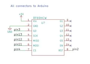
This accelerometer was connected to a PIC32, mounted on a small breakout board, which was soldered onto solder board, the main board for the belt interface. The accelerometer connects to the PIC32 over standard I2C connections. For the I2C hardware, we added pull up resistors to both the SDA and SCL lines to ensure proper functionality of both of the lines. The PIC32 then had separate outputs connecting to digital Arduino Uno pins that would write the states of the player’s hand position to the Arduino. This Arduino was also connected to an RF69HCW module, a radio with an extensive library through SPI. The connections to this include the CS, MISO, MOSI and other supporting circuitry as shown in Figure 13 in Appendix B.
Figure 5: Belt Hardware Interface Block Diagram
Both the Arduino and PIC32 were powered by two separate 9V batteries attached to the belt, in order to make the entire system wireless, which in turn allowed the player to be free to move around.
Base Station Hardware
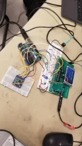
The base station hardware consists of four major hardware item as shown in Figure 6: the PIC32 connected to the Big Board PCB used in the course, a breadboard for all of the wiring, an Arduino, and the same RF module described in the belt hardware section. The RF Module (RFM69HCW) is connected to the Arduino through SPI with the MISO, MOSI, CS, and some additional pins necessary for support. The Arduino then outputs to the main PIC32 Big board. The PIC32 big board functions at a 3.3V functions level. The Arduino functions at a 5V level, so we used voltage dividers to both allow the PIC32 to receive a proper voltage level for the pins to read and for protection of the pins. The PIC32 big board contains the TFT which is used the for the display of the graphics for the project. Additionally, the PIC32 is connected to a button that moves through a game state, a potentiometer which is used to scroll through the varying screens, and an audio jack output which is used to connect to the speakers and to the DAC pin of the PIC32. Each of these pin connections except for the DAC connection is connected through a 330 Ohm resistor to protect the pin from high current inputs and ensure a pin on the big board does not get broke. The detailed schematic connection of this entire setup is shown in Figure 12 in Appendix B.
Figure 6: Base Station Interface Block Diagram
Results
In the final version of our project, we were able to have a fully functional game with a single glove working. The transmission of the data from the glove mounted accelerometer to the base station occurred fast enough that the game state was responsive within the time frame of a certain arrow being displayed on the screen. Extensive testing was done on each of the components to get to this end result.
The final state of the accelerometers allowed us to determine the direction that a player was moving their hand within a significant enough spatial range that a player could easily hit a direction state without the ranges of those states overlapping or becoming too large. After extensive testing, the optimal calibrated ranges of each of the given directional states were as shown in Figure 7.:
|
|
X-AXIS |
Y-AXIS |
Z-AXIS |
|
UP |
0 |
-64 |
0 |
|
DOWN |
0 |
64 |
0 |
|
LEFT |
60 |
0 |
0 |
|
RIGHT |
-65 |
5 |
5 |
Figure 7: Accelerometer Ranges
To confirm these results, each member of the team played through several rounds of the game. At some stages of the game, the Arduino would read all high values inputted from the PIC32, which did not correspond to any game state value. This was a common error, so we ensure that when this data was received from the Arduino we did not transmit this data. This occurred roughly 10% of the time, which we found to be too high a rate of failure. However, this rate is skewed because often the error state values would occur several times in a row, then stop occurring completely. We were not able to identify the source of this error, however it did not occur often enough to make the game unplayable.
The RF module also needed several rounds of testing to confirm functionality. Initially, the code was run with the transmission of a simple ‘Hello World’ string for functional verification. Following this, the correct data transfer was set up. An early stage image of the data transfer working correctly is shown below in Figure 8. The final result stage did not have the ‘?’ char at the end of the sent data, however.
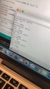
The final state of the RF transfer performed at a very high accuracy. We saw an packet sent out without confirming delivery only about 1 in 40 times. Additionally, the sending time was, on average, about 2 seconds. To confirm that the correct data was being received on the base station design during game play, we displayed the data on the screen. The entire system of accelerometer reading to data transfer performed very smoothly in the end. This can be seen in the video posted of our demonstration below.
https://www.youtube.com/watch?v=U7ztJEHCaIk&feature=youtu.be.
Another aspect of the project was sounds being played out of the DAC using DMA. The sounds themselves were implement using a set of sine tables of varying widths, each sampled at roughly 40kHz. The graphics of the game also performed very well, and we did not see any flickering during gameplay.
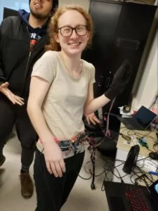
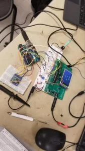
The final set up of our game functioned well, allowing our team member, Jennifer, to play through it successfully. In Figure 9 you can see Jennifer wearing the fully untethered input mechanism of the game. To address safety and electrical reliability in this device, we ensured that all the wires being used were completely covered by their original insolation, or manually applied electrical tape. The backs of all of the boards including the small board PIC32, Arduino, and solder board were covered in electrical tape as well. We did not have any safety concerns regarding the base station design primarily because it was stationary and all of the devices were properly connected. The fully functional base station is shown in Figure 10 with the TFT displaying the score after a round of gameplay. Additional images of the full hardware setup are also provided in Appendix G – Figures 14 and 15. These display the accelerometer glove and another image of the base station displaying the Start Menu.
Figure 9: Our team member Jennifer wearing the final set up
The concern for interference with other people’s designs is based primarily on RF interference. When using the RF modules we first checked to see if other people were using them at the time, however, the receiver code also checks to see if the packet being delivered over RF is the correct formatting for our project before reading the data. We could only see potential issues regarding this occurring if another group happened to use the same packet format as us. This did not occur during our testing. The only other potential source of interference for our design would be a space concern, which was another issue we did not run into. We also do not think that noise from other people’s projects would be a concern because of the high range of thresholds in our device.
Overall, the useability was good and fully functional, but definitely could have used some improvements. The user interface of the game performed very well, and we believed that this helped the game be very straightforward and simple to use. All members of the group were able to play the game, although in order to begin playing, the player occasionally had to adjust their arm dependent on the feedback given by the screen in order to ensure a position was hit. This outcome actually became desirable, as it helped make the game slightly more challenging. That being said, hitting the correct angle could occasionally be very difficult. Additionally, the belt that the user needs to wear is large and could potentially become uncomfortable to wear after long periods of time. Another point that we would like to further consider for the future and a potential redesign of the project would be accessibility for people who had a lower range of mobility or slower movement. To fix this issue in a redesign we could implement buttons to represent the arrows as we had used in our early testing stages. Additional ways of fixing this could be to adjust the accelerometer ranges so that a lower range of motion is necessary. Dependent of a person’s movement abilities, alternatives to a glove could be created to determine motion such as a sock or a hat. Another lack of accessibility issue with this design is the potential usability for visually impaired people. To mitigate this we could implement the game using audio and or haptic feedback.
Conclusion
Overall, our goal to create fun and engaging gesture pattern game was met, although there were a few set back that limited our performance. Our original idea had the player use both of their hands to match patterns, which would make the overall mechanics more difficult and engaging. However, I2C communication difficulties prevented us from integrating a second hand accelerometer. As you might see in several of our code structures, we were fully prepared for a second sensor, but an unknown error did not allow us to integrate it into the final game. The issue allowed the second sensor to communicate with and be read by the board, but it would only ever output a single value which would not change based on position. In the future, we would like to pursue another way to allow the player to use their other hand.
Another small detail that slightly disappointed us, was the speed of the radio. While it was effective at transferring the correct packets of information, it is not always timely. It is usable for our game and does work as we have explained, but it is slightly slower than we anticipated. For a movement game, we would have liked a faster way of communication, which is why we would have considered a faster wireless communication method in the future.Additionally, we would like to improve on the physical hardware design in the future and implement a potentially easier to wear belt with less hardware on the person.
However, we believe that our design did meet overall expectations because it was fully functional by the end of the lab. The accelerometers were able to accurately determine state of the hands, and transfer this data to the base station over RF. This data was then used consistently in the game to provide feedback for correct or incorrect position of the hands. Based on this functionality, we believe that we met our overall base expectations of our goal.
The most difficult aspects of this project were the set up of the accelerometers, and the overall integration of the entire system. The integration of the entire system had a large amount of failure points which needed to consistently be checked because there were a lot of different aspects to the project which were essential to the functionality of the entire project.
Safety and Legal Consideration
Given the large human interaction component with our hardware, we went to great lengths to ensure our interface was safe to use. Our belt has a solder board, which many of the electrical components are attached to. Therefore, we made sure to thoroughly electrical tap all exposed connections and wires that could harm the user or interface. However, it is not completely foolproof. The user must be wary of the long cable that connects the accelerometer glove and the belt. If it is pulled too hard, the equipment could be damaged. We made sure to make a length that accommodated for most lengths of arms, but the user must still exercise caution when interacting with our project.
In addition, as mentioned previously, our radios comply with FCC rule 15, since they are an unlicensed, low powered transmitter. They operate above 490kHz (915MHz) and have a removable, and replaceable antenna (a 3.5 inch solid core wire soldered to the breakout board).
Overall, our project did not have any negative ethical considerations. The game in the end was a fun game which a user could play and did not have a potential to harm another human being. Additionally our system was not autonomous so a large number of the aspects described in the IEEE standard did not apply to the project.
Schematics
Additional Photos
Source: Groovy Times

