
Summary of Cheap PIC Programmer
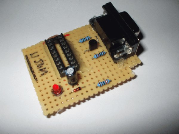
This article details a low-cost, error-free homemade programmer designed specifically for the PIC16F84 microcontroller. It requires minimal materials and tools, utilizing a standard RS232 serial connector and an IC board. The project includes an optional LED circuit for visual feedback. The build process involves soldering components onto the board according to a provided schematic, cutting the board to size, and securing connections with hot glue if desired.
Parts used in the Cheap PIC Programmer:
- IC Board
- RS232(Serial) FEMALE connector
- BC547B or 2N3904 Transistor
- 5.1 V diode
- 100 uF 16V Electrolytic Capacitor
- 18 PIN IC Socket
- 10Kohm resistor
- 15Kohm resistor
- Flashing red LED / 2.1 V Standard Red LED (Optional)
- 3.3Kohm Resistor (Optional)
- PIC16F84A Microcontroller
This programmer works only with PIC16F84 but it’s great because it never causes errors and works with almost all computers,unlike some other homemade programmers.
Step 1: Step one : Materials
For this programmer you won’t need many materials.In fact , you will find all you need in your local electronics shop 😉
So here’s what materials you will need:
-IC Board
-RS232(Serial) FEMALE connector
-BC547B or 2N3904 (I couldn’t find the BC so i used 2N3904,it works great)
-5.1 V diode
-100 uF 16V Electrolytic Capacitor
-10Kohm resistor
-15Kohm resistor
OPTIONAL[
-Flashing red LED / 2.1 V Standard Red LED
-3.3Kohm Resistor] -PIC16F84A Microcontroller
Tools:
-Soldering Iron
-Scissors or any other cuting toolOPTIONAL[
-Hot glue gun]
Step 2: Step two : The scheme
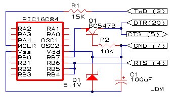
As you can see , i tagged two connection in the scheme as “Optional point” one and two .
Those are the points where you will connect the “Optional” circuit i will show you in step 3
Step 3: Step three : The optional circuit
The optional circuit consists of the LED and 3.3 Kohm resistor marked as optional in step one.
One pin of the resistor goes in the Optional point one , the other pin goes in the anode(+) of the LED.
The cathone(-) pin of the LED will go in Optional point two.
If you don’t understand , use the ellipse marked area of the scheme below.
Step 4: Step four : Let’s build it !
Ok , you’ve got all you need.Now it’s time to build it.
DON’T CUT THE IC BOARD YET!
First solder the RS232 female connector in a corner of your IC Board.If you don’t know what are the connectors of the RS232 i uploaded an image.
After you soldered the RS232 , solder all elements according to the schematic,and then cut the board.
After you cut the board,secure all solderings with hot glue (optional).
You’re done!
For more detail: Cheap PIC Programmer
- What materials are needed for this programmer?
You need an IC board, RS232 female connector, BC547B or 2N3904 transistor, 5.1 V diode, 100 uF capacitor, 18 pin IC socket, 10K and 15K resistors, and a PIC16F84A microcontroller. - Can I use a 2N3904 instead of a BC547B?
Yes, the author states that using a 2N3904 works great if the BC547B is unavailable. - How do I connect the optional LED circuit?
Connect one pin of the 3.3 Kohm resistor to Optional point one, the other to the LED anode, and the LED cathode to Optional point two. - Does this programmer work with all computers?
Yes, it works with almost all computers unlike some other homemade programmers. - When should I cut the IC board?
You should not cut the board until after you have soldered the RS232 connector and all other elements according to the schematic. - What tool is recommended for securing solderings?
A hot glue gun can be used to secure all solderings after cutting the board, though this step is optional. - What is the purpose of the optional points on the scheme?
These points allow you to connect the optional circuit consisting of an LED and a 3.3 Kohm resistor. - Which microcontroller does this programmer support?
This programmer works only with the PIC16F84 microcontroller.
