Summary of A Comprehensive VR Disability Accessibility Design Document
Summary (under 100 words): A foot-based VR controller is proposed to improve accessibility for users with arm or hand disabilities. It uses load-cell pressure sensors, HX711 ADCs, an ATMega328 microcontroller, and an FT232 USB-to-Serial adapter to convert foot pressure into XInput-compatible USB signals. Battery-powered, optionally Bluetooth-enabled sensors allow wireless use. The design emphasizes calibration, physical foot markers for blind repositioning, and software drivers to map and threshold inputs. Goals include robust microcontroller code, reliable signal identification, and a navigation system achieving 95% correct repositioning for first-time VR users.
Parts used in the Foot-Based VR Controller:
- Load cells (pressure sensors)
- HX711 AD Converter
- ATMega328 microcontroller
- FT232 USB-to-Serial adapter
- 9-volt battery (or 7–16V power source)
- 7805 voltage regulator
- USB cable
- Optional Bluetooth-to-Serial adapter (for wireless transmission)
- Physical sensor pad or strapped-on sensor housing
- PC driver and calibration software
Introduction
Problem and solution overview
As technological advancements propel the evolution of virtual reality (VR) devices, incorporating features such as full-body capture and haptic feedback, the potential for diverse applications in gaming, education, and resource management continues to grow. However, the current state of VR presents challenges for individuals with disabilities, particularly those affecting the arms or hands.
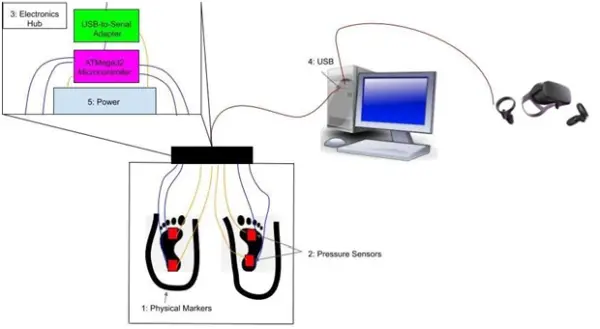
Addressing the accessibility concerns for people with arm or hand disabilities requires a multi-faceted approach. Our proposed solution focuses on creating a specialized controller for feet, employing pressure sensors for both continuous and rapid inputs. To facilitate signal parsing and identification, a USB driver is essential, and software can be utilized to save and normalize weight and pressure data, enabling calibration. The sensors will be equipped with dedicated battery packs to ensure power autonomy and minimize cord entanglement. Wireless data transmission may be achieved through a single Bluetooth device, albeit at the expense of increased power consumption. The signal gathering and transmission components include an ATMega328 microcontroller and a USB-to-Serial adapter, with the possibility of a Bluetooth-to-Serial adapter if Bluetooth is adopted.
The subsystems section of the proposal delves into various approaches for adjustability and accessibility, with testing required to determine the most user-friendly option. This includes the development of a stationary hub for feet, a combination of strapped-on sensors/battery packs, or a fusion of both, incorporating sensors on a pad akin to the Dance Dance Revolution format, providing physical markers for user guidance during controller use. Testing and design efforts in this project will focus on the first and third input options.
While there are existing disability-related controllers in the market, such as the QuadStick FPS game controller and the Microsoft Adaptive Controller, they are costly and not specifically designed for VR environments. Notably, the 3D Rudder Foot Motion Controller is currently the only foot controller for VR, yet it has received criticism for being challenging to control and prone to sliding on the ground. Our design aims to address these issues and enhance the user experience in VR for individuals with disabilities.
Primarily, individuals with upper body disabilities heavily rely on the 3D Rudder Foot Motion Controller, as it stands as the sole device addressing their specific needs in the current market [3].
The challenges associated with developing for virtual reality (VR) contribute to the scarcity of suitable controllers. Notably, VR controllers utilize a different software development kit (SDK) compared to controllers for established systems like PS4 and Xbox. Therefore, any new controller must be compatible with the VR headset. On the hardware front, controllers must be designed to accommodate users who may not see the device, ensuring stability and comfort during extended use. If a controller cannot be navigated without sight, it becomes impractical for individuals with the headset strapped to their face.
Additionally, general VR development challenges include maintaining a natural feel for users to enhance immersion and ensuring the durability of peripherals in response to users becoming deeply engaged, considering factors like the potential entanglement of wires or collisions with other objects.
High Level Requirements
1. Microcontroller Development:
– Develop code for the ATMega controller that is efficient, free of bugs, and capable of handling asynchronous inputs from the amplifiers.
2. Signal Identification:
– Design a driver that can identify signals for each user input and present them in a format compatible with other PC programs.
3. Navigation:
– Create a navigation system with physical markers that enables first-time users, while wearing a VR headset, to reposition their feet on the controller accurately. The goal is to achieve a 95% success rate in locating the correct sensing position if users move out of the initial position.
Design
Block Diagram
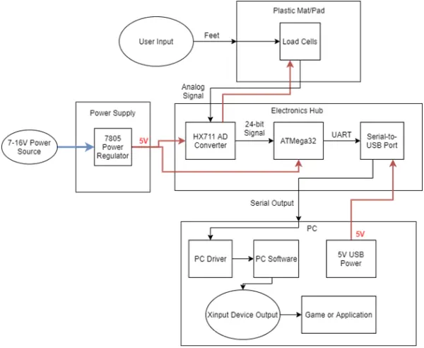
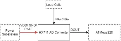
This schematic provides a comprehensive overview of the device at a high level. User input, generated by stepping on a pressure sensor, is transmitted as an analog signal to the HX711 AD Converter. The converter transforms this signal into a 24-bit digital format, making it suitable for processing by the ATMega328 Microcontroller. Subsequently, the microcontroller processes the signals into UART and transmits them to the USB to Serial converter, which further converts the signals into the USB protocol. The PC driver and software then interpret this USB signal into an XInput signal, making it compatible with various PC games or applications. This block diagram successfully fulfills all high-level requirements by effectively detecting user input and converting it into a signal usable in games or programs.
Block Descriptions
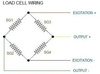
● Load Cells
This schematic provides a comprehensive overview of the device at a high level. User input, generated by stepping on a pressure sensor, is transmitted as an analog signal to the HX711 AD Converter. The converter transforms this signal into a 24-bit digital format, making it suitable for processing by the ATMega328 Microcontroller. Subsequently, the microcontroller processes the signals into UART and transmits them to the USB to Serial converter, which further converts the signals into the USB protocol. The PC driver and software then interpret this USB signal into an XInput signal, making it compatible with various PC games or applications. This block diagram successfully fulfills all high-level requirements by effectively detecting user input and converting it into a signal usable in games or programs.
Electronics Hub
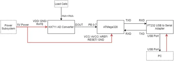
This component subsystem comprises an HX711 AD Converter, an ATMega328 Microcontroller, and a USB-to-Serial adapter. The HX711 is responsible for receiving input from the load cells and converting it into a 24-bit digital signal. Subsequently, this digital signal is transmitted to the ATMega328 Microcontroller, where data for each input is processed and then forwarded to the USB-to-Serial adapter through a UART signal. The Serial-to-USB adapter plays a crucial role in converting this signal into a USB Protocol, enabling the computer to interpret and process the data. The connection between the Serial-to-USB adapter and the PC is established through a USB cable. This subsystem holds significance as it processes the signals for transmission to the PC, allowing the drivers to accurately interpret the received signals.
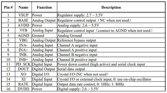
HX711 AD Converter
– Input Signals: INA+/- from Load Cells, 5V+/- 5% from the power subsystem
– Output Signals: Serial data transmitted to ATMega328
– Within the Electronics Hub subsystem, the HX711 serves the function of converting analog signals received from the load cells into a 24-bit digital signal, enabling further processing by the ATMega328.
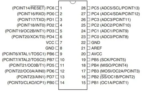
ATMega328
– Input Sources: A 24-bit digital signal sourced from the HX711 AD Converter, serial input received from the USB to Serial Adapter, and a 5V power input with a tolerance of +/-5%.
– Output Destination: The ATMega328, integral to the Electronics Hub subsystem, receives input data from the HX711 AD Converter and processes it for transmission to the FT232 USB to Serial Adapter via serial output.
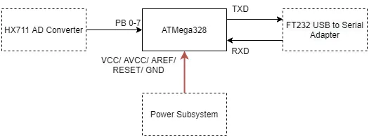
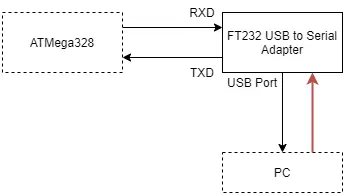
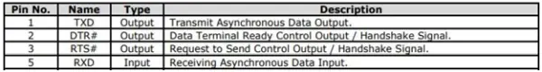
FT232 USB to Serial Adapter
● Inputs: The ATMega328 provides a USART Serial TTL signal, and the PC USB port supplies data and 5V with a tolerance of +/-5%.
● Outputs: The ATMega328 receives a serial signal, and a USB data signal containing preprocessed button signals is sent to the PC USB port.
● The FT232 USB to Serial Adapter, integrated into the Electronics Hub subsystem, plays a crucial role in converting and transmitting processed signals to the PC. This facilitates their utilization as inputs for games or applications.
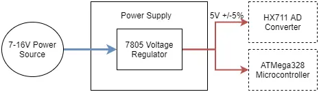
Power Supply
– Power Input Options: Accepts a 9-Volt Battery or any 7-16V power source.
– Power Output Specification: Provides a stable 5V +/-5% output for both the ATMega328 Microcontroller and HX711 AD Converter.
– All electronic subsystems within the device are designed to operate on a 5V +/-5% power supply. To meet this requirement, a 7805 Voltage Regulator will be employed to reduce the voltage from a 7-16V supply to a usable 5V level. The primary power source chosen is a 9-volt battery due to its portability and user-friendly nature.
The power requirements for each component is shown here:
| Device | Voltage/Current Requirements |
| HX711 AD Converter | 2.7~5.5V |
| ATMega328 Microcontroller | Maximum Operating Voltage: 6.0V
Typical Current Consumption at Vcc=5V: 4.0mA |
Table 3: Power requirements for all components on the device
USB Driver and Software
-Input Interface: The system receives a USB signal originating from the USB to Serial Adapter.
– Output Interface: The system produces a USB signal directed towards the USB to Serial Adapter.
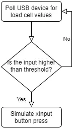
– Functionality of USB Driver and Software: The USB driver, in conjunction with software, serves the purpose of interpreting incoming data from both the microcontroller and sensors. Its primary function is to process this data into a format usable by programs on the connected PC. The USB driver must effectively decipher the data transmitted by the microcontroller, exposing it for utilization by secondary software. This secondary software is essential for translating the processed data into appropriate inputs for games or other software applications. Additionally, the software component must offer the capability to establish activation thresholds for each pressure sensor, ensuring that users across various weight ranges can use the device comfortably.
- What sensors are used to detect foot input?
Load cells (pressure sensors) are used to detect foot input, with signals sent to the HX711 AD converter. - How is the analog pressure signal converted for the microcontroller?
The HX711 AD converter transforms the analog load cell signal into a 24-bit digital signal for the ATMega328. - How does the device communicate with the PC?
The ATMega328 sends serial UART data to an FT232 USB-to-Serial adapter, which converts it to USB for the PC. - What power source does the design use?
The design uses a 9-volt battery or any 7–16V power source, regulated to 5V via a 7805 regulator. - Can the system be wireless?
Wireless transmission is possible using a Bluetooth-to-Serial adapter, but it increases power consumption. - What software functionality is required on the PC?
PC software/driver must interpret microcontroller data, expose it to applications, map inputs to XInput, and allow sensor threshold calibration. - How will users reposition their feet while wearing a VR headset?
The design includes physical markers on a sensor pad to enable repositioning; the navigation system aims for a 95% success rate. - Which microcontroller is used and what is required of its code?
An ATMega328 is used; its code must be efficient, bug-free, and handle asynchronous inputs from the amplifiers. - What role does the FT232 adapter play?
The FT232 converts the ATMega328 USART TTL serial signal into USB protocol so the PC can receive processed button signals. - Why is calibration necessary?
Calibration via software is needed to normalize weight and pressure data and set activation thresholds for different users.