
Summary of 8051-PIC MICROCONTROLLER PROJECTS
This article details the construction of a USB-based AVR In-System Programmer (ISP) designed to replace an older serial version. The project utilizes an FT232BM chip for USB connectivity and an ATtiny2313 microcontroller, programmed with Klaus Leidinger's firmware. It includes an optional serial EEPROM for customizing device names and uses AvrOspII software for programming various AVR devices.
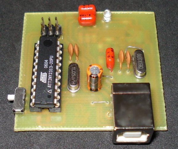
Parts used in the USB AVR ISP:
- FT232BM USB to RS-232 chip
- ATtiny2313 Microcontroller
- Serial EEPROM (IC1)
- USB-B Connector (CN1)
- 6-pin Connector (CN2)
- LED D1
- S1 Switch
- 11.0592MHz Crystal
- avr910_2313_v38c.hex Firmware file
USB AVR In-System-Programmer (ISP)
– The AVR firmware was written by: Klaus Leidinger
– The PCB was designed by: Dimitris Porlidas
– The schematic diagram was drawn by: Dimitris Porlidas
– The AvrOspII software was written by: Mike Henning
– Small modifications in firmware and schematic diagram were made by: Vassilis Serasidis
– The PCB was designed by: Dimitris Porlidas
– The schematic diagram was drawn by: Dimitris Porlidas
– The AvrOspII software was written by: Mike Henning
– Small modifications in firmware and schematic diagram were made by: Vassilis Serasidis
Nowadays, USB is the most popular connection connection between PC and peripherals such as AVR programmers, printers, scanners etc. For that reason I had to modify my old serial AVR In-System-Programmer (ISP) to work with USB connection. You can say, “use a USB to Serial adaptor to connect your AVR ISP with your PC”. Yes, that could be a solution but it would cost me more money than a singe FT232BM chip because I had to include an USB to RS232 adaptor and a power supply for my programmer. (almost €30).
So, the solution was to replace the two transistors, that were used to adapt the RS-232 voltage levels to TTL voltage levels, with a USB to RS-232 chip such as FT-232BM.
Initially, I used the John Samperi’s firmware V3.2 but afterwards I found out the Klaus Leidinger’s firmware that was a little bit faster. So, I chose the second one firmware but I had to modify the source code to work with 11.0592MHz crystal instead of 7.3724MHz that was initially designed because I couldn’t find this crystal in the market .
This programmer worked perfect with AVRprog but then I found a software that could support much more AVR devices than the AVRprog could program. This software is AvrOspII V5.47.
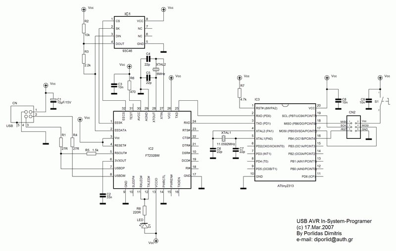
The circuit.
Following the schematic diagram that I read in the FT232BM manual I made the connections between ATtiny2313 and FT232BM. The FT232BM requires a few and ordinary components to work. When you connect this circuit to your PC you will see the message ” a new hardware was found” and then the factory name of FT232BM. IC1 is a serial EEPROM that used to store user’s settings. So, you can rename this programmer to be appeared as “AVR In-System-Programmer” or “MyAVR programmer”. Furthermore, you can add the firmware version of your circuit. Of cource, you can bypass this component because it’s optional. I saw that the programmer works with or without this EEPROM. Anyway, FTDI suggests you to use this EEPROM. Led D1 flashes when data are transmitted or received by FT232BM. CN1 is a USB-B connector and CN2 is a 6-pin connector to your target AVR (it is connected to the AVR to be programmed). The S1 switch is used to supply your target circuit with +5V from the USB connector of your PC. In this case you won’t need any additional power supply for your target circuit. Consider that a single USB port can supply up to 500mA current. You should not exceed this current limitation including the current that needs your AVR programmer too.
Programming the ATtiny2313.
Burn the ATtiny2313 with avr910_2313_v38c.hex file. Do not forget to deselect the “Devide clock by 8 internaly” option and select the “Ext. Crystal Osc. 14CK + 65ms” option on fuses section of your AVR programming software.
Optional: Configure the USB programmer.
As I said before, you can configure your programmer to be appeared with the name you want. In this case, my programmer is appeared as “AVR In-System-Programmer” when I plug it in to the USB port. Note that if you change any information on this screen you should change the same information in the “FTDIBUS.INF” and “FTDIPORT.INF” files. If you don’t make any modification to the EEPROM and you have Windows XP SP2 or newer operating system, you won’t need any driver. All the necessary drivers are included in your operating system.
The AvrOspII programming software.
The programming software that was chosen is AvrOspII V5.47 (currently version) because it supports a lot of AVR devices and the author of this software Mike Henning is keep on writing new versions supporting new AVR devices. You can see if there is a new AvrOspII version available Here.
For more detail: 8051-PIC MICROCONTROLLER PROJECTS
-
Why was the original serial programmer modified?
The modification was necessary because using a USB to Serial adaptor would cost nearly €30, whereas the FT232BM chip solution is more cost-effective. -
Which firmware was selected for this project?
Klaus Leidinger's firmware was chosen because it is faster than John Samperi's V3.2 version. -
What crystal frequency is required for the ATtiny2313?
An 11.0592MHz crystal is used because the originally designed 7.3724MHz crystal was unavailable in the market. -
Can the programmer work without the serial EEPROM?
Yes, the programmer works with or without the EEPROM, though FTDI suggests using one to store user settings. -
How do you supply power to the target circuit?
The S1 switch allows the target circuit to be supplied with +5V directly from the USB port, eliminating the need for an external power supply. -
Does Windows XP SP2 require additional drivers for this device?
No, if no modifications are made to the EEPROM, Windows XP SP2 or newer operating systems include all necessary drivers automatically. -
What software is recommended for programming AVR devices?
AvrOspII V5.47 is recommended because it supports many AVR devices and receives updates from the author Mike Henning. -
What fuse settings must be applied when burning the ATtiny2313?
You must deselect the Devide clock by 8 internaly option and select the Ext. Crystal Osc. 14CK + 65ms option.
