Introduction
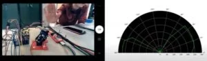
For our final project, we created a spy robot: a robot that uses remote radar sensing to detect intruders. The physical system consisted of the servo setup we had from lab 4, a time-of-flight distance sensor (discussed in depth below), and the PIC32 microcontroller. The distance sensor was affixed to the servo setup and the microcontroller controlled the servos so the assembly could pan back and forth to get distance readings over a set range of angles. Then, this data was stored and sent to the python backend via serial communication to plot the data as a radar map. The data was sent after every full pan so the radar was updating to reflect the environment it was sensing in real time. Thus, the user could view this radar map remotely and detect if there were any intruders based on a change in the radar map.
The motivation for the project was to create an embedded solution to a real-world problem: use the PIC to build a real-time remote surveillance system for users to monitor a room. As IoT systems have gained popularity, so has the desire to have surveillance systems that can be remotely accessed. This project explores the implementation of a basic level of this type of system.
Design
High Level Design
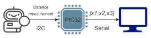
The Spy Robot’s main purpose is to be used as a surveillance system using a time-of-flight (TOF) sensor. We wanted to create a real-time LIDAR-like graph that showed a top view of the room. This task was made more interesting given we had never actually been in that room during this semester. The TOF sensor, mounted on a miniature robot controlled by SG90 servo motors, collects distance data by scanning the room bidirectionally and sends it to the PIC32 via I2C, then the PIC processes this data and sends it to the lab PC via serial communication. The PIC32 is responsible for controlling the scanning pace of the robot, collecting the data in an array, and sending the array to the lab PC. This scanning data is processed in a Python script that generates a polar coordinate graph of the room.
Due to the modularity of this project, we needed to make trade-offs at every step to ensure an optimal operation of the Spy Robot. We chose the TOF sensor specifically because of its performance accuracy and rapid communication via I2C, for a great price. Thus, we ensured an optimal performance from our peripheral device. The bottleneck came from how fast we could plot data. Due to the time constraints and difficulty debugging in a remote environment, we began by building a generalizable model that could be improved relatively easily. This included plotting an array of values at once, updating our graph with each sweep of the room, rather than real-time plotting several points. This is because real-time plotting would have required sending an escape character, or an encoded message from the PIC to signal the start and direction of a new sweep. We have real-time serial data plotting code worked out, but integrating it with the sensor data was beyond the scope of our project. Another reason we chose to plot arrays corresponding to each sweep is because this is a much more accessible way to start creating a 3D map. Adding the capacity to move the robot’s head vertically could be done fairly easily given how we have set up our code. One of the biggest challenges in engineering is to build something useful that will withstand the test of time. This was our mentality with our design decisions, and guided a lot of our hardware/software trade-offs. We wanted to ensure that this could be useful to us later, or to others in the future.
As stated previously, our project loosely resembles the concept of IoT home surveillance technology. One great example of this technology is Ring. Ring is a product that allows users to see who is at their door through a video camera so they can see who is there even if they are not home. This device is activated by motion detection. Even though it can record video for a long duration of time, it only notifies the user when there is a potential person at the door. Our project is similar in the sense that it remotely detects intruder detection, but it does not provide notifications or video like Ring. In that way, it mimics radar as used for submarines in that it shows the environment including changes in that environment.
Software Design
Main Function
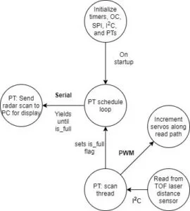
The main function consists of the setup and initialization of all of our timers, our PWM channels for our servos, the I2C channel, the protothreads and scheduler, the serial channel, and the sensor. In this function, two protothreads are added to the scheduler: the timer thread and the dataread thread. Our send_data thread is used to send the radar data to the python backend from the PIC. Our dataread thread is used to pan our robot back and forth and collect distance readings while doing so.
VL53L1X Library
One of the core structural choices we made for this project was to port the Sparkfun Arduino library for this sensor over to the PIC32. This library, in turn, implemented the STMicrocontrollers API for the chip. We viewed the API implementation as unnecessarily specific for us to learn while the arduino level library interfaced with the hardware at a level that was more consistent with this class. This was also a very worthwhile exercise because porting libraries from one architecture to another is a skill that will be directly applicable in future projects. With this library specifically, we found that all of the functions were sensor specific except for the very base unit of I2C reading and writing that was specific to the arduino. By changing this base unit to PIC32 I2C commands instead of arduino, we only had to make minimal changes to the rest of the library to get it to work. We found this approach to be really effective and still taught us a lot about the sensor and how I2C works at a low level.
Debugging
We found a timing issue in the I2C_Write()’s that was accidentally solved with our debugging print statements. Ref 5 in the Appendix shows a table that lists the “Bus free time between transmissions” to be 1.3ms. It turns out, with the vast numbers of print statements we had written to diagnose the problem, we had accumulated over 1.3ms of delay between transmissions. Upon commenting them out since the problem was solved, we no longer were able to read the distance. After extensive debugging and a good deal of paranoia, we replaced the prints with delays to isolate the problem to a timing issue, then found this figure in the datasheet. Knowing the cause, we finally solved this issue by adding a delay(2) to both the I2C read and write commands to impose this down time requirement on the bus.
One key tool we used in the debugging process was the Picoscope. The Picoscope was instrumental in allowing us to see how the I2C interface was working. The scope has a feature on it that will decode the signals on the I2C bus and show what addresses the PIC is reading or writing from and what information is being written or read. This was an invaluable tool because it allowed us to check that the physical signals being sent were correct compared to what we could see on the serial output. At one point in our project, we were getting correct reads with our I2C but the serial print statements showed that there was a shift in the I2C reads: our first read would get a 0 from the bus, then the next read would get the value from the first address we were reading from. This issue was resolved on the C end as the I2C was shown to be working properly on the Picoscope.
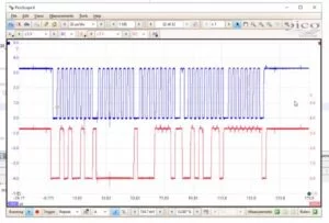
This is how our debugging on the picoscope started – counting bit by bit. We later saved I2C settings to the scope and used the built-in interpreter
The other key strategy we used to test this system was to set up an additional sensor with an arduino at home. Because of the remote work environment we weren’t able to interact directly with the hardware, making it difficult to understand certain things about the sensor. By hooking up an identical sensor to an arduino running the arduino library that we ported over, we were able to see how the sensor and the library was supposed to work. This also allowed us to test out different features of the library before we copied them over like messing with the region of interest (ROI) and the sample rate. It is of note that the hardware setup we had at home was deliberately not the same as the setup we accessed remotely. We decided to set up a simplified system at home to fill in the gaps of what we could test and play around with using the remote system.
Hardware
Hardware Setup
Due to the remote nature of the course this semester, we tried to keep minimal hardware setup. This is why we thought the Sparkfun Distance Sensor would be a good choice – a lot of the setup is already done for us with this integrated board. We also intend to extend the Lab 4 hardware setup with the servos, so this setup is both simple and familiar. The only new interface we would have to set up is I2C which is unfortunately hardware setup as the only interface on the breakout board. Our SPI connections for data transmission are the most involved, and most important, part of the hardware setup, so we have carefully detailed these in an Altium Schematic. The sensor and microcontroller connections are shown below, and the full schematic can be found in the Appendix.
HW/SW Tradeoff
Although we all love working with hardware, the remote working environment constrained the amount of hardware work we could do. Our final design mounted the distance sensor on the servo assembly from lab 4 (with googly eyes included of course). Still wanting to incorporate hardware into our project, we leveraged the work from previous labs to limit the amount of setup required by the course staff. Additionally, this limited the amount of hardware debugging we would have to do, which is very difficult to do remotely.
Sensor Selection
We surveyed many potential sensors before landing on this one. We started with the HC-SR04 ultrasonic sensor as the go to arduino range sensor. After looking at the specifications more closely however, we decided to broaden our search and look for a sensor that was more reliable and precise. We were also interested in working with LIDAR but those state of the art sensors get quite large and expensive. Searching on sparkfun and adafruit for arduino compatible sensors (because we knew they would be compatible with the PIC32 and have existing infrastructure to work with) and found several good options. We eventually settled on the VL53L1X infrared time of flight (TOF) sensor from STMicrocontrollers that was setup on a sparkfun breakout board. This sensor has a fantastic range of 4m and millimeter precision for only $20. These specifications allowed us to sweep our radar sensor across the room and measure small changes in the environment. The relatively cheap price enabled us to purchase a second sensor for debugging in our remote work environment, which proved very useful at solving certain issues.
The sensor works by pulsing an infrared laser and clocking the “time of flight” of the laser to return to the sensor with a SPAD array.
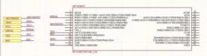
Microcontroller Schematic
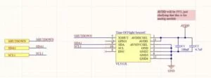
Sensor Schematic
Source: 4760 Final Project: Spy Robot