
Summary of PicoDetector : a PIC-based simple and cheap metal detector
Summary: This project replaces a PIC microcontroller's crystal with a coil to form a metal-sensitive oscillator. The PIC watchdog is used as a stable time reference; by comparing the oscillator loop count against a calibrated value, the circuit detects nearby metal and lights an LED. Calibration occurs on power-up, and a dual-color or two LEDs indicate calibration and detection states. Source code for PIC12 (mikroC PRO) and basic wiring notes are provided.
Parts used in the PicoDetector:
- PIC12 microcontroller (PIC12 family)
- Coil L1 (inductor to replace crystal; try various coils)
- Dual-color LED D1 (or two separate LEDs)
- Resistors (for LED current limiting as required)
- Power supply (battery or appropriate Vcc for PIC12)
- PCB or perfboard and wiring
- Optional: programming tool for PIC12 (ICSP programmer)
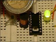
A short video clip is sometimes better than a long explanation :
The idea of this circuit is to hack PIC oscillator circuit, by replacing the crystal by a coil : the frequency of the oscillator then depends on presence of metal near the coil, just like in a classic metal detector.
To detect changes of main oscillator frequency, we use the PIC watchdog as internal time reference.
By comparing both oscillators frequencies, we can know if a piece of metal is near the coil, and then light a LED.
It shares the same idea as PicoBat, the ultrasonic bat detector.
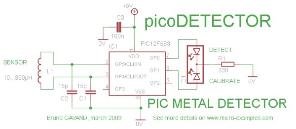
 Circuit Schematic
- Coil L1 replaces crystal in PIC oscillator circuit : try with the coils you have to find the best one ! if calibrate LED blinks on power up, it works.
- D1 is a dual color LED, replace with two classic LEDs if you don’t have one.
C Source code
/*
 ************************************************************
 * picoDetector: an ultra-simple and cheap metal detector
 ************************************************************
 *
 * Author : Bruno Gavand, april 2009
 * see more details on http://www.micro-examples.com/
 *
 * source code for mikroC PRO compiler V1.65
 * feel free to use this code at your own risks
 *
 * target : PIC12, oscillator in HS mode, watchdog enabled
 *
 * PIC PIN Assignemnt :
 *
 * GP0 : detect LED indicator
 * GP1 : calibrate LED indicator
 * GP2 : NC
 * GP3 : NC
 * GP4, GP5 : inductor
 *
 ************************************************************
 */

#define MAXTRY 15
// number of watchdog restart to calibrate loop counter

unsigned char   ctr ;
// number of loops between two watchdog resets
unsigned char   previous ;
// previous value of ctr
unsigned char   calibr ;
// calibration value when oscillator runs free
unsigned char   restarts ;
// number of watchdog restarts
unsigned char   en ;
// enable flag, allows detection

/*
 * main loop
 */
void    main()
        {
        unsigned char   i ;


        /*
         * configure GPIO as digital port
         */
        CMCON0 = 7 ;
        ANSEL = 0 ;
        TRISIO = 0 ;
        GPIO = 0 ;

        /*
         * power up ?
         */
        if(STATUS.NOT_TO)
                {
                /*
                 * yes, init variables
                 */
                restarts = 0 ;
                calibr = 1 ;
                }

        /*
         * watchdog reset counter
         */
        if(restarts < 255) restarts++ ;

        /*
   * if counter differs too much from calibration value
         */
        if((previous ^ ctr) > calibr)
                {
                /*
                 * turn detect LED on
                 */
                GPIO.F0 = en ;

                /*
                 * if not on power up
                 */
                if(STATUS.NOT_TO == 0)
                        {
                        /*
                         * while in calibration mode
                         */
                        if(restarts < MAXTRY)
                                {
                                /*
                                 * shift calibration value
                                 * and wait a little bit
                                 */
                                calibr <<= 1 ;
                                Delay_ms(5) ;
                                }
                        }
                else
                        {
                        /*
                         * turn detect LED off
                         */
                        GPIO.F0 = 0 ;
                        }
                }

        /*
         * save last counter
         */
        previous = ctr ;

        /*
         * is calibration over ?
         */
        if(restarts > MAXTRY)
                {
                /*
                 * yes, turn calibrate LED off
                 * and set enable flag
                 */
                GPIO.F1 = 0 ;
                en = 1 ;
                }
        else
                {
                /*
                 * no, turn calibrate LED on
                 * and clear enable flag
                 */
                GPIO.F1 = 1 ;
                en = 0 ;
                }


        /*
         * set watchdog prescaler
         */
        OPTION_REG = 0b11111001 ;

        /*
         * start counter, to be interrupted by watchdog
         */
        ctr = 0 ;
        for(;;)
               {
               ctr++ ;
               }
        }

For more detail:  PicoDetector : a PIC-based simple and cheap metal detector
/*
* set watchdog prescaler
*/
OPTION_REG = 0b11111001 ;
/*
* start counter, to be interrupted by watchdog
*/
ctr = 0 ;
for(;;)
{
ctr++ ;
}
}
For more detail: PicoDetector : a PIC-based simple and cheap metal detector
- What is the sensing element in this metal detector?
The coil L1 replaces the crystal in the PIC oscillator and acts as the sensing element; its frequency shifts when metal is near. - How does the circuit detect metal?
By comparing the PIC oscillator frequency (affected by the coil) with the PIC watchdog time reference and detecting changes in the loop counter. - Can I use a dual-color LED for indicators?
Yes, D1 is a dual-color LED; you can replace it with two classic LEDs if you don't have one. - How is calibration performed?
Calibration runs on power-up for a number of watchdog restarts (MAXTRY), shifting the calibr value while the calibrate LED is on. - Which PIC pins are used for LEDs and coil?
GP0 is detect LED, GP1 is calibrate LED, and GP4 and GP5 connect to the inductor. - What compiler and PIC target does the source use?
The source code is for mikroC PRO compiler and targets a PIC12 with oscillator in HS mode and watchdog enabled. - How does the code indicate detection?
When the loop counter differs from the calibration value beyond the threshold, the detect LED is turned on via GPIO.F0. - What should I do if the LED blinks on power up?
If calibrate LED blinks on power up, it indicates the coil/oscillator is working and you should try different coils to find the best one.
