Introduction
On this page a circuit is described, making it possible to interface a PIC and a PS/2 mouse. If you send me a request (read further), it is possible to obtain for free also the assembler program to communicate with the PS/2 mouse. The PIC microcontroller used to test and develop the communication with the PS/2 mouse is a 20MHz PIC 16F877, but, as it is a non-critical application, a wide set of other PICs (maybe everyone) and other microcontrollers should be suitable, too. In the article Host – PS/2 mouse hardware communication, a description of the protocol used to communicate with a PS/2 mouse is reported.
Take care: PS/2 devices differ from serial mice, concerning both communication protocol and electric levels; in PS/2 mice levels used for supply and data are 0 and +5V, in serial mice RS-232 levels are used, +12V and -12V. This article deals with a PS/2 mouse. Also the PIC must be fed with +5V supply. In details, common (or ground) pins of PIC and PS/2 mouse must be connected together; the same for +5V pins.
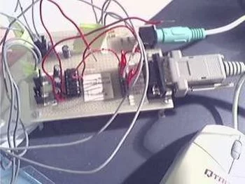
To develop and use the assembler program I have used a 20 MHz 16F877 PIC mounted on the Development Board v. 1.2, by me designed and built, described in the article PIC 16F877 Development Board v.1.2 on this site.
Take care to connections, to avoid unpleasant damages to devices! Before damaging a PIC or a mouse, if you are not really sure of acting correctly you can mail me.
| Acknowledgement and disclaimers
The material reported in these pages is the result of preliminary tests, project developement and verify carried on by the undersigned in first person. Concerning the assembler program, I guarantee the absolute originality of the material, though obviously not excluding that on the net something analogous could be found. Being this material at free disposal of whoever desires it, it is absolutely forbidden any form of use for commercial purposes without asking for permission (e-mail); please read further the “The assembler program” section. I don’t assume, of course, any responsibilty for possible direct or indirect damages to things or persons deriving by the use of the informations contained in this article. PIC and Microchip are registered trademarks. The assembler program has been developed with the free software MPLAB v. 5.61.00 from Microchip. The schematic of the interface circuit with a PS/2 mouse has been designed with TARGET 3001! (400 pins license). |
The interface circuit
The circuit used to communicate with a PS/2 mouse is quite simple. Supply is the same than the PIC’s one (+5V and GND). The K2 connector in the schematic must be connected to two of the PIC’s I/O pins; in details, the assembler program uses two I/O pins on PORT A, but NOT open collector type pins. The PS/2 protocol settles that Clock and Data must be open collector lines, so to make it possible to drive them by both the host and PS/2 device without any electrical problem (as an example, if the host drives the clock low for a given time when also the mouse is driving it, it means the host wants to gain the control of the communication); being the PIC’s pins used NOT open collector, these two lines must never be driven high by the PIC. What follows refers both to Clock and Data lines. In order for the line to rise at the high logic level (as it should be when the line is in the inactive state), driven high by the pull-up that you can see in the schematic, the related PIC’s pin must be put into high impedance state, that is, it must be set as input. In order to drive low the open collector line, the PIC must drive low the related pin, that is, to set that pin as output and to impose on it a zero. In case a programming error is made, imposing a high logic level on the pin, should the mouse drive low the same line, the 330 Ohm protection resistor would limit at about 15 mA the current sourced by the PIC’s pin, so avoiding you the need to buy a new PIC. Please, note: this possibility has not been tested.
Clicking on the link below the figure, an enlarged image will be displayed in a new window.
To print the schematic you can also save it and then open it again with the browser or another program; check anyway the size of the print with the print preview (if possible).
For more detail: Mouse interfacing and communication using PIC16F877
About The Author
Ibrar Ayyub
I am an experienced technical writer holding a Master's degree in computer science from BZU Multan, Pakistan University. With a background spanning various industries, particularly in home automation and engineering, I have honed my skills in crafting clear and concise content. Proficient in leveraging infographics and diagrams, I strive to simplify complex concepts for readers. My strength lies in thorough research and presenting information in a structured and logical format.
Follow Us:LinkedinTwitter