The role of power supply is crucial for electronic circuits because without sufficient power, the circuit cannot function at its optimal level. On the other hand, an exceeded power supply can deteriorate the circuit components by heating effect. There are usually two choices for power supply topologies; Linear Power Supply and Switched Mode Power Supply (SMPS).
The linear power supply is traditionally an old topology, thus it had its presence in the design and architecture of older electronic components. But the new Switched Mode Power Supply topology is preferred over Linear Power Supply for current circuit designs due to its increased efficiency and compact size. However, the SMPS has more components and complex design still its advantages outweighs the linear power supply.
Also, the cost of SMPS was high initially
but with the birth of the electronic age, component costs have dropped so low that the high raw material content of copper and iron in the linear transformer has made the SMPS technology more cost-effective.
We saw the introduction of SMPS technologies by Microchip’s A1114 application note, which described the working of SMPS circuits in December 2015. The application note highlights the applications of various SMPS technologies and the design specifications of components for SMPS. It also suggests the factors for consideration while selecting SMPS topologies.
Switched Mode Power Supply Topology
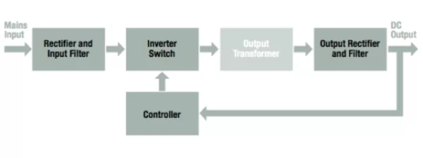
As Switch Mode Power Supply contains a large number of components, thus it needs different stages. Every stage takes care of all the factors necessary for optimal performance. Example: If the input supply is AC, then the input stage has a provision of rectifier and low-pass filter for AC to DC conversion. There is also an inverter stage available for DC to AC conversion by simultaneous switching DC voltage on and off. The rate of switching decides the frequency of the AC output.
We also saw the Open Electronics’ Switched Mode Power Supply known as Torpedo, with a SEPIC configuration. Its circuit structure came with three different stages; Input Stage, Battery Charger, and SEPIC Converter. A transition from battery power to another source without interruptions was one of the unique features of the Torpedo circuit.
Read more: SWITCHMODE POWER SUPPLY TOPOLOGIES EXPLAINED

