
Summary of Relay Timer with PIC16F628
This article describes a 0–99 minute relay timer built with a PIC16F628A microcontroller running at 4.0 MHz via an external crystal. It features a 16×2 HD44780 LCD for display and setup, controlled by three tact switches on RB0 (Start/Stop), RB1 (Unit), and RB2 (Ten). Activating the timer triggers a logic high on RA3 to drive a relay.
Parts used in the Relay Timer with PIC16F628:
- PIC16F628A microcontroller
- External 4.0 MHz crystal
- HD44780 based 16×2 character LCD
- Three tact switches
- Relay
- RA3 pin interface
Here is 0 to 99 minutes relay timer using PIC16F628 microcontroller and 16 character LCD display. The microcontroller is PIC16F628A running at 4.0 MHz clock using an external crystal. An HD44780 based 16×2 character LCD is the main display unit of the project where you can watch and set the timer duration using tact switch inputs. There are three tact switches connected to RB0 (Start/Stop), RB1 (Unit), and RB2 (Ten) pins. You can select the timer interval from 0-99 min using Unit and Ten minute switches. The Start/Stop switch is for toggling the timer ON and OFF. When the timer gets ON, a logic high signal appears on the RA3 pin, which can be used to switch on a Relay. The circuit diagram of this project is described below.
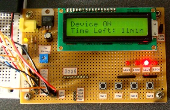 There are three tact switches connected to RB0 (Start/Stop), RB1 (Unit), and RB2 (Ten) pins. You can select the timer interval from 0-99 min using Unit and Ten minute switches. The Start/Stop switch is for toggling the timer ON and OFF. When the timer gets ON, a logic high signal appears on the RA3 pin, which can be used to switch on a Relay. The circuit diagram of this project is described below.
Build Accurate LC Meter and start making your own coils and inductors. This LC Meter allows to measure incredibly small inductances making it perfect tool for making all types of RF coils.  LC Meter can measure inductances starting from 10nH – 1000nH, 1uH – 1000uH, 1mH – 100mH and capacitances from 0.1pF up to 900nF. The circuit includes an auto ranging and reset function to make sure the readings are as accurate as possible .
For more detail: Relay Timer with PIC16F628
- What is the maximum duration this timer can measure?
The timer allows selecting an interval from 0 to 99 minutes. - How do I start or stop the timer?
Press the tact switch connected to the RB0 pin labeled Start/Stop. - Which pins control the minute inputs?
The Unit switch connects to RB1 and the Ten switch connects to RB2. - Does the circuit use an internal or external clock?
The microcontroller runs at 4.0 MHz using an external crystal. - Can this project trigger an external device?
Yes, a logic high signal appears on the RA3 pin when the timer is ON to switch on a relay. - What type of display is used in this project?
An HD44780 based 16×2 character LCD is used as the main display unit. - Is there an LC Meter included in this specific build?
No, the LC Meter is mentioned only as a separate tool for measuring inductances and capacitances.
