
It is good idea to build a simple and low cost DIY remote controlled real time clock/calendar using simple components. This post show how to make a remote controlled real time clock using PIC12F1822 microcontroller, DS1307 RTC chip, NEC IR remote control and all data are displayed on 1602 LCD.
The DS1307 is an 8-pin integrated circuit uses I2C communication protocol to communicate with master device which is in our case PIC12F1822 microcontroller. This small chip can count seconds, minutes, hours, day, date, month and year with leap-year up to year 2100.
The DS1307 receives and transfers data (clock data and calendar data) as BCD format, so after receiving data we have to convert these data into decimal data, and before writing data to the DS1307 we have to convert this data from decimal to BCD format. For example we have the BCD number 33, converting this number into decimal gives 21.
PIC12F1822 has an I2C hardware module which can work as master device. The I2C bus specifies two signal connections:
Serial Clock (SCL) (pin RA1)
Serial Data (SDA) (pin RA2)
The time and date informations are displayed on 1602 LCD display. This LCD is interfaced with the microcontroller using 74HC595 shift register as what was done in this post:
Interfacing PIC12F1822 microcontroller with LCD display
The IR remote control used in this project uses NEC communication protocol. The following post shows how this protocol works and how to decode its data with PIC12F1822:
Extended NEC Protocol Decoder Using PIC12F1822 Microcontroller
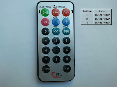
An image of the remote control used in this project with used buttons data is shown below. Only 3 buttons are used in this project and the rest of buttons have no effect on the circuit.
Components List:
- PIC12F1822 Microcontroller
- NEC Protocol IR Remote Control (Example: Car MP3)
- DS1307 RTC
- 1602 LCD
- 74HC595 Shift Register
- IR Receiver
- 47µF Capacitor
- 32.768 Crystal
- 3V Lithium Coin Cell Battery
- 10K Variable Resistor
- 3 x 10K Resistor
- +5V Power Supply
- Protoboard
- Jumper Wires
Remote controlled real time clock using PIC12F1822 and DS1307 circuit:
For this project internal oscillator of the microcontroller is used and MCLR pin is configured to work as a digital input pin.
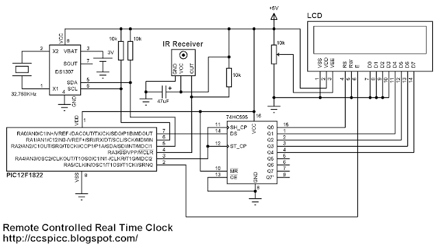
The IR receiver has 3 pins: GND, VCC (+5V) and OUT. The OUT pin is connected to RA3 pin of PIC12F1822. The IR receiver is used to receive IR signals comes from the remote control and sends data to the microcontroller.
Read more: Real Time Clock/Calendar with Remote Control
