
Summary of PIC16F877 PWM (2 channel) code and Proteus simulation
This article explains how to generate two PWM channels using the PIC16F877 (CCP1 and CCP2), provides C code compiled with HI-TECH C in MPLAB, and includes a Proteus simulation. Using a 20 MHz crystal yields ~4.9 kHz PWM; RC2/CCP1 outputs 50% duty and RC1/CCP2 outputs 75% duty. Downloads for code and simulation are provided.
Parts used in the PIC16F877 2-channel PWM project:
- PIC16F877 microcontroller
- 20 MHz crystal
- Proteus simulation software (Proteus v7.10)
- MPLAB IDE (MPLAB v8.85)
- HI-TECH C compiler (v9.83)
- Connections to RC2/CCP1 pin
- Connections to RC1/CCP2 pin
- Power supply for PIC16F877
This post answers the question, “How to make a pulse width modulator using PIC16F877” ?
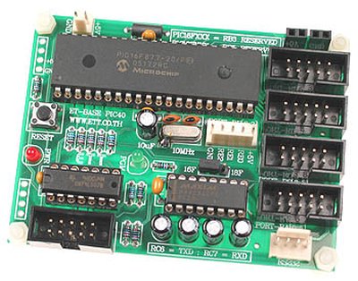
Also, using PIC16 simulator (Proteus) you can verify this PWM code and change it according to your needs. You can download the complete project code and Proteus simulation from the ‘Downloads‘ section at the bottom of this page.
This PIC16F877 microcontroller tutorial provides the 2 channel PWM code (using C language) and Proteus simulation ( written using MPLAB and HI-TECH C compiler ). There are many uses for PWM signal, e-g you can control dc motor speed using PWM. CCP is the name for the built in PWM module in PIC16F877. There are 2 built in PWM modules available, namely CCP1 and CCP2. This code is using both CCP1 and CCP2 modules to generate 2 separate PWM signals.
It is assumed that you know how to blink an LED with PIC16F877 microcontroller. If you don’t then please read this page first, before proceeding with this article.
The following diagram (made in Proteus) shows the PWM generator circuit diagram.
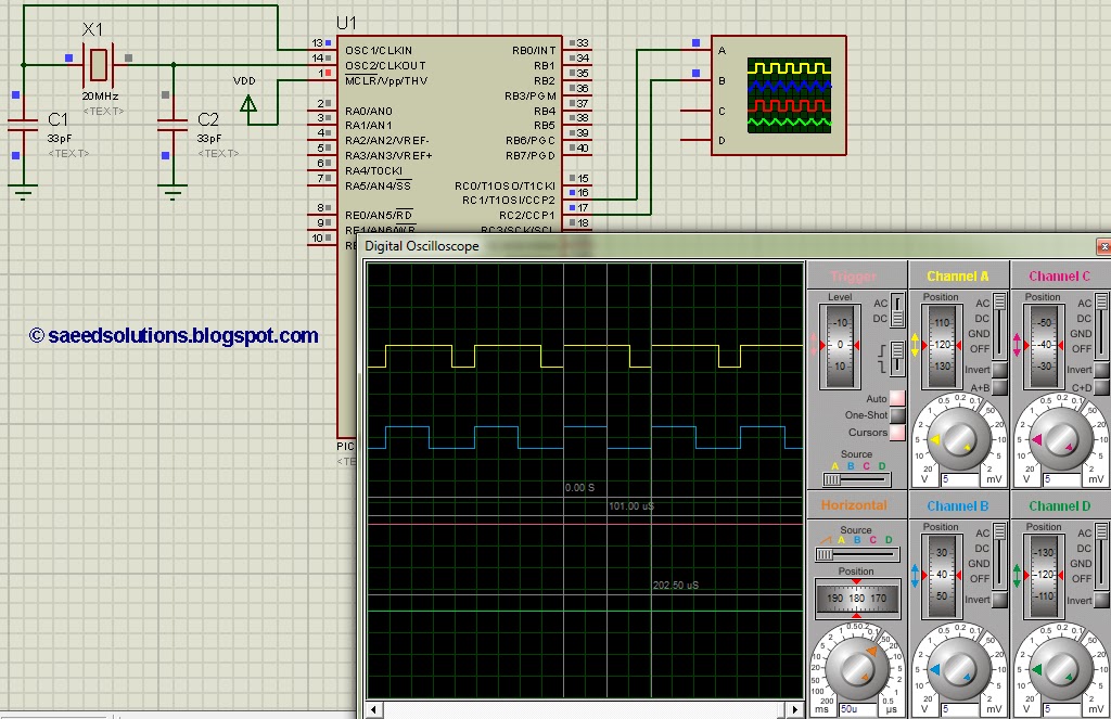
A crystal of 20MHz is used here with PIC16F877. As we know that any PIC micro controller has an architecture which executes an instruction in 4 CPU cycles, hence this 20Mhz crystal makes this PIC16F877 run at 5MIPS (Million of instructions per second). In the above figure, it is clear that a PWM of 4.9kHz frequency with 50% duty cycle is being generated at RC2/CCP1 pin and a PWM of 4.9kHz frequency with 75% duty cycle is being generated at RC1/CCP2 pin.
Code
The code for main function is shown below.
Downloads
2 channel PWM code using PIC16F877 was compiled in MPLAB v8.85 with HI-TECH C v9.83 compiler and simulation was made in Proteus v7.10. To download code and Proteus simulation click here.
For more detail: PIC16F877 PWM (2 channel) code and Proteus simulation
- How many PWM channels does the PIC16F877 tutorial demonstrate?
The tutorial demonstrates two PWM channels using CCP1 and CCP2. - What clock/crystal frequency is used for the PIC16F877 in this project?
A 20 MHz crystal is used. - What PWM frequency is achieved with the 20 MHz crystal?
The PWM frequency is approximately 4.9 kHz. - What duty cycles are generated on RC2/CCP1 and RC1/CCP2 in the example?
RC2/CCP1 is set to 50% duty and RC1/CCP2 is set to 75% duty. - Which pins output the PWM signals in this project?
RC2/CCP1 and RC1/CCP2 pins output the PWM signals. - Which compiler and IDE were used to compile the project code?
The code was compiled using HI-TECH C v9.83 in MPLAB v8.85. - Can the provided PWM code be tested in simulation?
Yes, the project includes a Proteus simulation for verification. - Where can I download the complete project code and simulation?
The article provides download links in the Downloads section at the bottom of the page.
