
Summary of PIC16F84A i2c (bit banging) code and Proteus simulation
This article presents software-based I2C implementation (bit-banging) for the PIC16F84A microcontroller using C in MPLAB with HI-TECH C. It details a Proteus simulation where RA4 serves as SDA and RB0 as SCL, both pulled up with 10K resistors. The code initializes pins, sends a start bit, writes address 0xA0, reads a byte (0xFF due to no slave), acknowledges, and stops.
Parts used in the PIC16F84A i2c bit banging project:
- PIC16F84A microcontroller
- RA4 pin (SDA)
- RB0 pin (SCK)
- 10K resistors
- MPLAB v8.85
- HI-TECH C v9.83 compiler
- Proteus v7.10 simulator
- I2C Debugger Tool
This post provides the i2c bit banging code for PIC16F84A microcontroller. As we know[1], PIC16F84A microcontroller doesn’t have any built in i2c modules, so we have to create it in the software. This code is written in C language using MPLAB with HI-TECH C compiler. You can download this code from the ‘Downloads‘ section at the bottom of this page.
It is assumed that you know how to blink an LED with PIC16F84A microcontroller. If you don’t then please read this page first, before proceeding with this article. It is also assumed that you know how i2c protocol works, if you don’t then please read this page first.
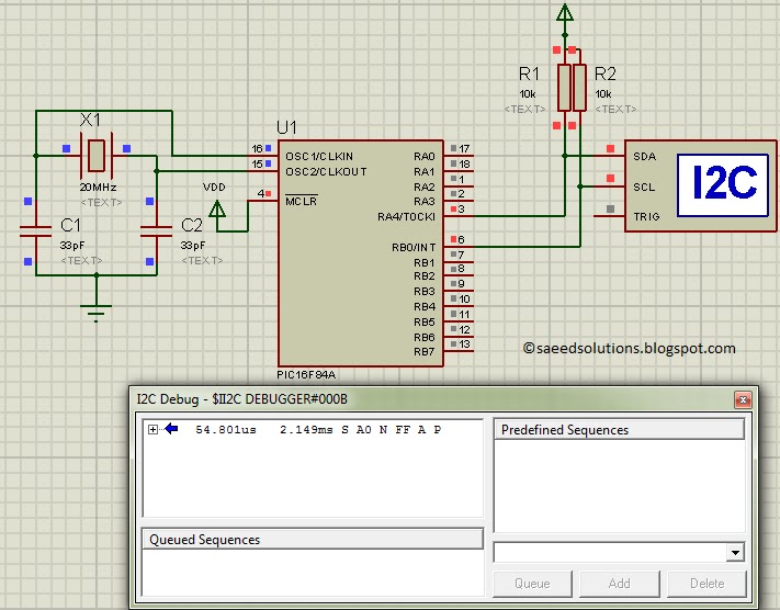
The result of simulating the code in Proteus is shown below.
In the above circuit[2], RA4 pin is being used as SDA pin and RB0 pin is the SCK pin. Both of these pins are pulled up using 10K resistors as required for i2c protocol. Proteus provides an ‘I2C Debugger Tool‘ which is attached on the SDA and SCK pins in the above circuit. This i2c debugger tool receives all the i2c messages and displays them on the ‘I2C Debug‘ window displayed in above figure. Close up image of this ‘I2C Debug‘ window is shown below in the figure.
In the above figure, ‘I2C Debugger Tool‘ is telling us that first of all it received i2c start bit S. Then a value of 0xA0 was received. After that, there was a NACK bit (named as N in the above figure). After the NACK, a value of 0xFF was there on i2c bus. After that, an ACK was there (named as A) in the above figure, and in the end i2c stop bit (named as P) was received. When this Proteus simulation started then after 54.801usec PIC16F84A started sending this i2c data and stopped at 2.149msec time.
Code
The code for the main function is shown below.
In the main function, firstly i2c pins are initialized using InitI2C() function. Then I2C_Start() function sends a start bit S on i2c bus. Then a value of 0xA0 is written on the i2c bus using I2C_Write_Byte(0xA0); statement. After that, I2C_Read_Byte() function reads a byte from the i2c bus, because there is no slave attached on the i2c bus, that is why RxByte will receive a value of 0xFF[3]. After that, an ACK ‘A‘ is transmitted on i2c bus using I2C_Send_ACK() function. And in the end a stop bit ‘P‘ is transmitted on i2c bus using I2C_Stop() function.
Downloads
I2C code for PIC16F84A was compiled in MPLAB v8.85 with HI-TECH C v9.83 compiler and simulation was made in Proteus v7.10. To download code and Proteus simulation click here.
For more detail: PIC16F84A i2c (bit banging) code and Proteus simulation
- Why is software I2C needed for PIC16F84A?
The PIC16F84A microcontroller does not have any built-in I2C modules. - Which pins are used for SDA and SCL in this project?
RA4 pin is used as SDA and RB0 pin is used as SCK. - What resistor value is required for the I2C lines?
Both pins are pulled up using 10K resistors as required for the I2C protocol. - What tool displays I2C messages in the simulation?
Proteus provides an I2C Debugger Tool attached to the SDA and SCK pins. - What value does RxByte receive when no slave is attached?
RxByte receives a value of 0xFF because there is no slave attached on the I2C bus. - What compiler was used to compile the I2C code?
The code was compiled using HI-TECH C v9.83 compiler within MPLAB v8.85. - How long did the PIC16F84A take to send data in the simulation?
The PIC started sending data after 54.801usec and stopped at 2.149msec.
