
Summary of PIC12F1822 DAC Module
This article explains how to initialize and control the Digital-to-Analog Converter (DAC) module on the PIC12F1822 microcontroller using the CCS PIC C compiler. It details configuration modes, voltage sources (VDD, VREF, FVR), and the use of `setup_dac` and `dac_write` functions to generate analog output levels on the RA0 pin.
Parts used in the PIC12F1822 DAC Project:
- PIC12F1822 Microcontroller
- DAC Module
- RA0 Pin
- VSS Supply Voltage
- VDD Supply Voltage
- VREF Pins
- FVR (Fixed Voltage Reference)
- CCS PIC C Compiler
This small post shows how to start using PIC12F1822 DAC (Digital-to Analog Converter) module.
PIC12F1822 microcontroller has 1 DAC module. The DAC can be used to supply analog voltage on RA0 pin with 32 selectable output levels.
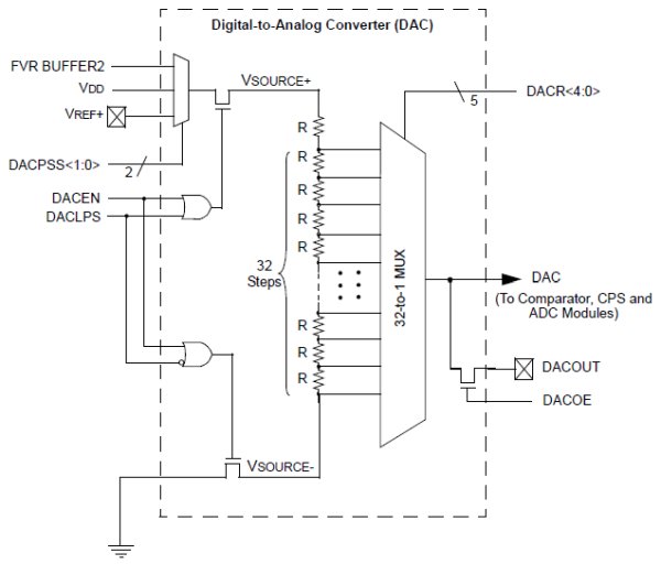
The input of the DAC can be connected to:
- External VREF pins
- VDD supply voltage
- FVR (Fixed Voltage Reference)
DAC Block diagram is shown below:
With CCS PIC C compiler we can initialize the DAC module using the following command:
setup_dac(int8 mode);
Where mode can one of the following modes:
DAC_OFF 0 // DAC disabled
DAC_VSS_VDD // Negative source is VSS and positive source is VDD
DAC_VSS_VREF // Negative source is VSS and positive source is Vref+ pin
DAC_VSS_FVR // Negative source is VSS and positive source is FVR (Fixed Voltage Reference)
The DAC output can be enabled using the following line which or’ed with above in setup_dac() using |.
DAC_OUTPUT // Enable ADC output on RA0 pin.
Controlling the output of the DAC is also easy with CCS PIC C compiler and for that we have to use the following command:
dac_write(int8 value);
Where value should be a 5-bit number which varies between 0 and 31.
The DAC output voltage is determined by the following equation assuming that the DAC is enabled (DACEN bit is 1):
Assume that we’ve PIC12F1822 microcontroller with +5V power supply, the DAC is configured with VSS and VDD as negative and positive sources and the DAC output is enabled.
Minimum Vout voltage when DACR[4 : 0] = 0b00000 equals to 0V.
Maximum Vout voltage when DACR[4 : 0] = 0b11111 equals to 4.84V
Writing DACR[4 : 0] = 0b00000 is done using: dac_write(0);
And DACR[4 : 0] = 0b11111 is dac_write(31);
PIC12F1822 DAC Module Example:
This is a small example for the DAC module. Example circuit schematic is shown below.
Read more: PIC12F1822 DAC Module
-
How many DAC modules does the PIC12F1822 have?
The PIC12F1822 microcontroller has one DAC module. -
What are the possible input sources for the DAC?
The input can be connected to External VREF pins, VDD supply voltage, or FVR. -
Which command initializes the DAC module in CCS PIC C compiler?
The setup_dac(int8 mode) command is used to initialize the module. -
How do you enable the DAC output on the RA0 pin?
You enable it by ORing the DAC_OUTPUT flag with the mode in the setup_dac() function. -
What value range is required for the dac_write function?
The value must be a 5-bit number varying between 0 and 31. -
How is the maximum output voltage calculated in a +5V system?
With VSS and VDD sources, the maximum voltage at dac_write(31) equals 4.84V. -
What is the minimum output voltage when the DAC is enabled?
The minimum voltage is 0V when DACR[4 : 0] is set to 0b00000. -
How many selectable output levels does the DAC provide?
The DAC provides 32 selectable output levels.
