


Summary of PIC PROGRAMMER MkV using PIC12F629
The PIC Programmer MkV is an affordable entry into microcontroller programming, utilizing only 12 components and a small matrix board. It supports 8-pin (PIC12F629/675) and 18-pin (PIC16F628/675) chips via an IC-Prog software interface on a desktop computer with a DB-9 serial port. The device uses LEDs for visual status and requires removing the chip from the target project for programming.Parts used in the PIC Programmer MkV:
- Desktop computer with DB-9 serial port
- IC-Prog 105C-a software
- PIC12F629 or PIC12F675 chip
- PIC16F628 or PIC16F675 chip
- Matrix board
- 470R resistor
- Female plug
- 4-core telephone cable
- Three red LEDs
- Voltmeter
PIC Programmer MkV is designed to get you into PIC Programming for just a few dollars. It uses just 12 components. Most of them will be in your "junk-box" and the PC board is a small piece of matrix board. It's the cheapest way to get started.
As well as PIC PROGRAMMER MkV you will need these 4 things:
1. A desk-top computer with DB-9 serial port. (This programmer will not work on a lap-top computer and may not work with Vista.)
2. A software program called IC-Prog 105C-a and some helpful notes to guide you with setting up your computer. (This project is not suitable for In-Circuit Programming. You need to remove the chip from the project you are creating and program it in the 18 pin socket on the programmer. Eight pin chips are fitted with pin 1 aligning with pin 1 of the socket.)
3. A PIC chip, either PIC12F629 or PIC16F628 and
4. A project using one of these micros.
This will get you into producing a MICROCONTROLLER PROJECT.
We have concentrated on two PIC chips. An 8 pin and 18 pin chip. The 8 pin chip can be either PIC12F629 or PIC12F675 and the 18 pin chip is PIC16F628 or PIC16F675.
The programmer will work with many other chips but we are concentrating on these two types to get you started.
Not only is a microcontroller project simpler than using lots of discrete chips, but it can be cheaper and easier to modify and provide a greater range of features than lots of individual chips.
On top of this you can produce a project that requires a program and this can be "locked" from prying eyes. This makes it saleable and you can protect your Intellectual Property - and make money.
Talking Electronics has produced a range of simple projects and provides assistance to get you into programming and creating projects that you have only "dreamed of."
Getting into microcontroller programming will change your life.
But before we go any further, let's build the programmer:
BUILDING THE PIC PROGRAMMER
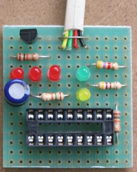
The circuit is constructed on a small piece of matrix board. All the components are readily available and the 3 red LEDs act as a visual indication that the programmer is operating as well as creating a 5v rail for the chip. The other two LEDs indicate the clock line is operating and 13v is present on the programming pin. It does not indicate the actual voltage - you will need to measure the voltage with a voltmeter to determine this.
A 470R resistor is connected between pins 4 and 8 inside the plug. This allows 4 lines to be taken to the project.
WIRING THE PLUG AND LEAD
The lead can be any 4-core cable. We have used 4-core telephone cable. Follow the diagram to prevent any mistakes. The 470R resistor is soldered to pins 4 and 8 of the female plug.
For more detail: PIC PROGRAMMER MkV using PIC12F629
- Can this programmer work on a laptop computer?
No, the programmer will not work on a laptop computer. - Does the programmer support In-Circuit Programming?
No, this project is not suitable for In-Circuit Programming. - What software is required to set up the computer?
You need a software program called IC-Prog 105C-a. - Which PIC chips are best for beginners using this programmer?
The article concentrates on the 8-pin PIC12F629 and the 18-pin PIC16F628. - How do you verify if 13v is present on the programming pin?
You must measure the voltage with a voltmeter as the LED does not indicate the actual voltage. - What type of cable should be used for the lead?
Any 4-core cable can be used, such as 4-core telephone cable. - Where is the 470R resistor connected inside the plug?
The resistor is connected between pins 4 and 8 inside the plug. - What function do the three red LEDs serve?
They act as visual indication that the programmer is operating and create a 5v rail for the chip.
Related projects
DHT11 Low Cost Humidity Sensor using PIC16F628A with Proteus Simulation
IntroductionThis microcontroller project demonstrates how to interface a low-cost DHT11 temperature and humidity sensor with a PIC16F628A using a Proteus simulation environment.The...
Motors & Robotics · PIC12F629RGB LED PWM Driver for High Power 350mA LEDs using PIC12F629
Description This project combines a PIC and three constant current 'buck' converters to produce an RGB LED controller that will operate with...
LCD & Display Projects · PIC16F628AFrequency Counter by PIC16F628
In this project we are building a basic and low cost frequency counter circuit . It can measure from 16Hz to 100Hz...
Programmers & ICSPCalculator Test using PIC24FJ64GA006 with Proteus Simulation
Introduction The Calculator Test using EASYHDL is a practical microcontroller project built on the PIC24FJ64GA006 and simulated in Proteus. This project demonstrates...
Programmers & ICSPPID Controlled Oven using TMS320F28027PT with Proteus Simulation
IntroductionThis project demonstrates a PID controlled oven implemented using a PICCOLO TMS320F28027PT microcontroller and verified through Proteus simulation.It is a practical microcontroller...
Programmers & ICSPPICCOLO Motor Controller Sample Design using TMS320F28023PT with Proteus Simulation
IntroductionThis project demonstrates a PICCOLO motor controller sample design implemented using the TMS320F28023PT Piccolo microcontroller and tested through Proteus simulation. It focuses...

Ibrar Ayyub
I am an experienced technical writer holding a Master's degree in computer science from BZU Multan, Pakistan University. With a background spanning various industries, particularly in home automation and engineering, I have honed my skills in crafting clear and concise content. Proficient in leveraging infographics and diagrams, I strive to simplify complex concepts for readers. My strength lies in thorough...