Summary of Mastering Microcontroller Programming: From Basics to Advanced Techniques
The paper presents an Enhanced Automatic Programmer (EAP) that integrates circuit design, block-based business logic, mikroC code generation, compilation, and direct hex-file burning for PIC microcontrollers (e.g., PIC18F442, PIC18F4520, PIC18F542). Built in Java/NetBeans using OpenBlocks, EAP automates configuration code, supports Proteus validation, and provides a visual toolbox, flow editor, and burn utility; a calculator case study demonstrates creating a project, wiring LCD/keypad to ports, generating code, compiling to hex, and loading the firmware.
Parts used in the Enhanced Automatic Programmer (EAP):
- NetBeans (development environment)
- Java (programming language)
- OpenBlocks library
- MikroC PRO (compiler/integration for compilation)
- QL-PROGen (hex burning tool integration)
- Proteus Design Suite (for simulation/validation)
- PIC microcontrollers (PIC18F442, PIC18F4520, PIC18F542)
- Component toolbox items: LED
- Component toolbox items: LCD-8bit
- Component toolbox items: Keypad
- Component toolbox items: Stepper motor
- Component toolbox items: Seven-segment display
ABSTRACT
A microcontroller, comprising a CPU, RAM, ROM, and I/O ports, is a compact computer integrated into a single circuit board. Its significance in various aspects of daily life cannot be overstated. Unlike general-purpose computers, microcontrollers are specifically designed to carry out predefined tasks or run single applications. They are integral components in a plethora of automated products, such as engine control systems, remote controls, power tools, toys, and office equipment like photocopiers, printers, and fax machines.
While individuals working in electronics may possess familiarity with microcontrollers, they may not necessarily possess proficient programming skills for them. Programming a microcontroller involves utilizing various software tools, such as Proteus for circuit design, mikroC PRO for coding, and QL-PROGen for burning hex files onto the microcontroller. Consequently, programming a microcontroller can be a challenging endeavor for such individuals.
Our project aims to enhance an automatic programmer tool [1] that generates mikroC code and corresponding hex files from a block diagram. This upgraded tool offers an integrated platform allowing users to design circuit diagrams, generate code, and directly burn hex files onto the microcontroller. It provides a selection of blocks for constructing business logic, which serves as input for code generation. Furthermore, it facilitates code compilation and direct burning of hex files onto the chip.
The tool features microcontrollers like PIC18F442, PIC18F4520, and PIC18F542, placed within the Circuit Diagram Window for easy access and integration into projects.
INTRODUCTION
A microcontroller, often referred to as a computer-on-a-chip or single-chip computer, embodies the fusion of “micro,” denoting its compact size, and “controller,” signifying its role in managing objects, processes, or events. Alternatively known as embedded controllers, these devices, along with their supporting circuits, are frequently integrated into the devices they govern. Microcontrollers find extensive application across diverse domains of everyday life. Virtually any device involved in measurement, storage, control, calculation, or information display is a potential candidate for microcontroller integration [1].
One of the most prevalent uses of microcontrollers is in automobiles, where they play a pivotal role in engine control and often manage various other systems within the vehicle. In desktop computing, microcontrollers can be found within peripherals such as keyboards, modems, printers, and other external devices. Similarly, consumer electronics ranging from cameras to compact disc players and ovens commonly incorporate microcontrollers, showcasing their versatility across a broad spectrum of products [1].
Conceptually akin to the microprocessors found in personal computers, microcontrollers differ in that they encompass not only the CPU but also integral memory and I/O interfaces within a single chip. Due to the inherent limitations in chip size, microcontrollers are typically employed in smaller systems. Prominent examples of widely used microcontrollers include Intel’s 8052, Motorola’s 68HC11, and Zilog’s Z8 [1].
The inception of the microcontroller dates back to 1971, credited to the collaborative efforts of engineers Gary Boone and Michael Cochran at Texas Instruments. Their creation, the TMS 1000, was a groundbreaking 4-bit microcontroller featuring built-in ROM and RAM. Initially utilized internally within TI’s calculator products, the TMS 1000 was subsequently refined and offered for sale to the broader electronics industry in 1974 [8]. Intel, a key player in microcontroller development, introduced significant models such as the 8048 in 1976, which served as the processor in the IBM personal computer keyboard. Following this, the 8051 emerged in 1980 and became one of the most renowned microcontroller families, with its architecture still in production today [8].
The 1990s witnessed a paradigm shift with the advent of microcontrollers equipped with electrically erasable and programmable ROM (EEPROM) memories, including flash memory. These advancements allowed for convenient programming, erasure, and reprogramming using only electrical signals, eliminating the need for specialized hardware and enabling in-circuit programming. This flexibility facilitated software upgrades without requiring device removal, thus streamlining software development and reducing costs. Present-day microcontrollers, exemplified by offerings from Microchip and Atmel, commonly incorporate flash memory technology, epitomizing the evolution and versatility of microcontroller technology.
Apart from conventional devices, there’s a growing trend in the production of specialized microcontrollers tailored for specific sectors like automotive, lighting, communications, and low-power consumer gadgets. Moreover, microcontrollers have undergone significant advancements in terms of size and performance. For instance, Atmel unveiled a flash microcontroller as small as 2 mm by 2 mm in 2010. These diminutive microcontrollers are both compact and cost-effective, making them suitable for integration into products ranging from toys to toothbrushes [8].
In light of the increasing demand for microcontroller applications, the task of programming these devices has become pivotal. To streamline this process, we have developed the initial iteration of an automatic programmer [4]. This software tool enables users to generate mikroC code tailored for the PIC microcontroller after constructing a customized block diagram, subsequently producing the corresponding Hex file. The block diagram comprises interconnected blocks, each representing a distinct component of the system. These diagrams, whether simple or intricate, offer a clear visualization of system elements and their interconnections, facilitating both individual component analysis and overall system performance evaluation [5].
For validating the generated mikroC code, the Automatic Programmer leverages Proteus Software. In this endeavor, we have enhanced the automatic programmer functionality, detailed in Section 4. The structure of this paper is as follows: Section 2 provides a comprehensive overview of microcontroller programming. Section 3 elucidates the functionality of the automatic programmer [4]. Section 4 delineates the enhancements made to the automatic programmer and illustrates their utilization. Furthermore, Section 5 presents a case study involving a calculator application utilizing the improved automatic programmer. Finally, Section 6 encapsulates the conclusions drawn from this endeavor.
2. EXISTING SYSTEM
2.1 Using a Microcontroller
3. AUTOMATIC PROGRAMMER
To streamline this process, Hussain et al. introduced a software tool known as the Automatic Programmer [4]. This tool enables users to produce mikroC code for PIC microcontrollers following the creation of a desired circuit diagram, subsequently generating the hex file upon compilation. Its primary advantage lies in its automated generation of configuration code, such as the setting of direction registers, eliminating the need for users to manually write such code. Moreover, the tool simplifies the process by automatically creating the hex file.
Previously, users had to rely on three distinct software tools for circuit design, chip programming, and hex file burning. With the Automatic Programmer, users could design circuits and generate configuration code, albeit lacking a mechanism for incorporating business logic, a feature introduced in the enhanced version of the automatic programmer. Additionally, the original version of the automatic programmer lacked a mechanism for directly burning the hex file onto the chip, necessitating the use of separate software for this purpose.
4. ENHANCED PROGRAMMER
The Enhanced Automatic Programmer (EAP) represents an advancement over the previously developed software known as Automatic Programmer. EAP serves as an all-in-one platform facilitating the design of circuit diagrams, configuration of components (e.g., setting direction registers via mouse-click inputs without the need for manual code writing), creation of block diagrams wherein users define the functionality algorithm by connecting blocks, and direct burning/loading of hex files onto the microcontroller.
A block diagram comprises interconnected blocks, with each block representing a distinct component or segment of the system. These diagrams offer a simplified means to represent even complex systems, aiding in understanding the function of individual elements as well as the overall system performance. Given their simplicity and versatility, block diagrams are extensively utilized by control engineers for modeling various dynamic systems [5].
To validate the generated micro C code, the corresponding circuit is replicated within Proteus software, and the generated code is loaded onto the microcontroller for simulation. Labcenter Electronics Ltd., established in 1988, developed Proteus, a comprehensive software suite. Notably, the Proteus Design Suite uniquely offers the capability to co-simulate both high and low-level microcontroller codes within the context of mixed-mode SPICE circuit simulations. SPICE (Simulation Program with Integrated Circuit Emphasis) serves as a widely used open-source analog electronic circuit simulator. Proteus’s Virtual System Modeling (SVM) encompasses a microcontroller programming tool environment, incorporating a plethora of software features and hardware options [6].
4.1 Enhanced Programmer Development
Developed within the NetBeans environment using Java, this software leverages OpenBlocks for interface design, enabling users to create block diagrams representing their input algorithms. OpenBlocks, an open-source Java library, specializes in the creation of block-based programming interfaces and comprises two core packages: codeblocks and slcodeblocks. Codeblocks serves as the foundational library responsible for the majority of functionality [7].
Verification and compilation of the source code generated by this software are carried out using Mikro C Pro commands. The resulting hex file from compilation serves as the output for burning into the microcontroller, a process integrated with QL-PROGEN.
The Enhanced Automatic Programmer (EAP) boasts a user-friendly visual interface encompassing a Component Toolbox, Circuit Diagram Window housing microcontrollers, Display Code Window for showcasing generated code, and a Make Flow Window. Users can construct circuit diagrams using components available in the toolbox, including LED, LCD-8bit, Keypad, Stepper motor, and seven-segment displays. Notably, microcontrollers such as PIC18F442, PIC18F4520, and PIC18F542 are pre-embedded within the Circuit Diagram Window.
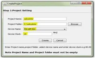
Once the circuit diagram is finalized, users establish connections between components and the microcontroller while configuring component properties. Upon diagram completion, configuration code is automatically generated and displayed in the Display Code Window. Users initiate by creating a project directory where the generated source code is saved as a “.c file,” accompanied by another file named “.mcppi,” which contains configuration settings. Both files are essential for compilation. Users specify the PIC microcontroller type (e.g., PIC18F442, PIC18F4520) and set its frequency before saving the project with a designated name. Subsequently, users input the algorithm via block connections provided in the toolbox, clicking on “update code” to merge business logic and configuration code seamlessly.
4.2 Using Enhanced Programmer
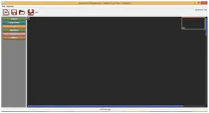
By selecting the “Create Project” option from the File menu, a new window will prompt the user to establish a project directory. Upon project creation, the main window displays with the microcontroller positioned at its center. Adjacent to the main window, on the left side, lies the component toolbox featuring elements discussed earlier in Section IV for constructing circuit diagrams. The right side of the main window presents a workspace where the microcontroller is initially placed, awaiting the addition of other components from the toolbox as per the input algorithm requirements. Users can employ drag-and-drop functionality to position desired components onto the workspace.
Upon right-clicking any component, three options emerge: 1) Delete Component, 2) Drag Component, and 3) Set Component Property. Through the “Set Component Property” option, users can configure component properties, such as specifying LED ports and pins. Once all components are configured, basic code generation occurs by utilizing the “Generate Code” button located atop the menu bar. The generated code, constituting basic configuration code for devices attached to the microcontroller, is viewable in the code tab view.
To construct a logical flow diagram, users access the “Make Flow Diagram” window from the code tab view. This window incorporates a Component toolbox housing block designs of conditional and logical statements, logical operators, and function blocks like “getselectedkey” for keypad input retrieval and “writeonlcd” for displaying content on an LCD screen. After creating the flow diagram, clicking “Update Code” generates logical code, subsequently merging it with configuration code to form the final source code.
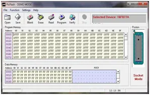
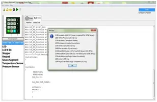
Compiling this source code involves utilizing the compilation button from the menu bar, resulting in the production of a .hex file. Finally, selecting the “Burn Code” button from the menu bar initiates a new window prompting the user for required information and accepting the .hex file as input for burning it into the microcontroller.
5. CALCULATOR CASE STUDY
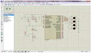
To begin, construct a block diagram for a calculator incorporating an LCD display and keypad functionality. Navigate to the list of components and drag the LCD and keypad modules onto the viewport. Adjust their properties to establish connections with the microcontroller.
The keypad is linked to port B, while the data ports of the LCD are connected to port C. Additionally, the RS bit of the LCD is connected to bit 0 of port D, and the E bit is connected to bit 1 of port D, as illustrated in Figure 5.
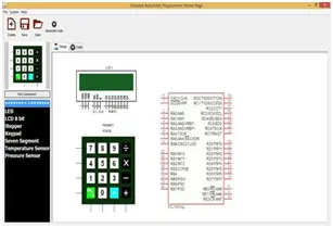
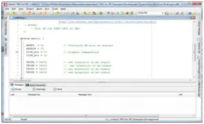
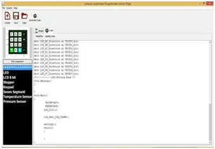
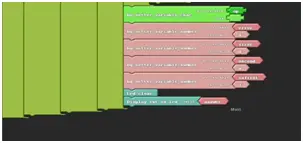
Once the microcontroller connections are established, utilize the “generate code” button to generate fundamental configuration code. This configuration code sets the direction registers to designate inputs or outputs. Additionally, for the keypad, the code generated will include the method for detecting the pressed keys, enabling the retrieval of key values through a simple function call. The initialization of the LCD is also included in the configuration code, as illustrated in Figure 6.
Next, click on the “make flow” button within the code tab. This action will prompt the opening of another window dedicated to facilitating the creation of a flow for the calculator algorithm, as outlined earlier in the software. To construct algorithm flows using blocks, our software leverages an open-source library called openblocks.
The software interface presents six distinct tabs (Control, Components, Logic Operators, Number, Utilities) on the left-hand side of the screen. The Control tab encompasses conditional statements (such as if, if-else) and loops (including for, while), while the Components tab offers helper methods for hardware components like LED control, stepper motor rotation (clockwise and counterclockwise), keypad operations (such as detecting clicks and retrieving clicked keys), LCD control (e.g., clearing the display and turning it on).
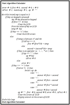
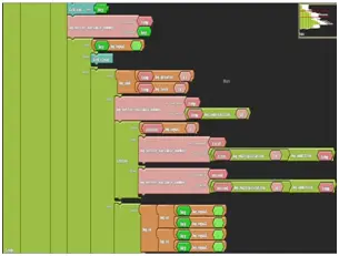
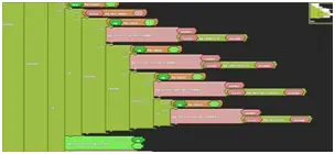
Begin constructing the algorithm flow for the calculator on the viewport, utilizing the available blocks from the aforementioned tabs. The algorithm utilized for the calculator operation is elucidated in Figure 7.
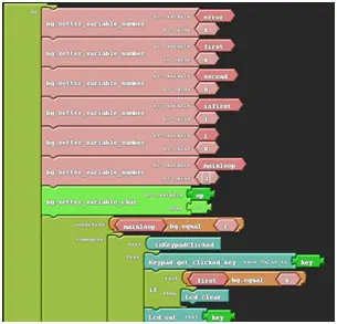
- What does the Enhanced Automatic Programmer do?
It integrates circuit design, block-based business logic, mikroC code generation, compilation to a hex file, and direct burning of the hex file onto PIC microcontrollers. - Can I design circuit diagrams inside EAP?
Yes, EAP provides a Component Toolbox and a Circuit Diagram Window to design circuits and place microcontrollers. - How is business logic created in EAP?
Business logic is created by composing block diagrams using OpenBlocks in the Make Flow Window and then updating code to merge with configuration code. - Which microcontrollers are included in the Circuit Diagram Window?
PIC18F442, PIC18F4520, and PIC18F542 are pre-embedded in the Circuit Diagram Window. - How does EAP generate configuration code?
When components are placed and their properties set, clicking Generate Code produces automatic configuration code such as direction register settings and component initialization. - How is the generated code compiled to a hex file?
The generated source code is compiled using Mikro C Pro commands to produce the .hex file. - Can EAP burn the hex file directly to a microcontroller?
Yes, EAP includes a Burn Code option that opens a window to accept the .hex file and burn it to the microcontroller via QL-PROGEN integration. - Is simulation supported for the generated code?
Yes, the generated mikroC code can be validated by replicating the circuit in Proteus and loading the code onto the microcontroller for simulation. - What components are available in the toolbox for building projects?
The toolbox includes LED, LCD-8bit, Keypad, Stepper motor, and seven-segment displays among other blocks and helper methods.