
Summary of Low Cost Solar Lighting Controller
This article details a low-cost, autonomous solar lighting controller built around the PIC12F675 microcontroller. Designed to manage power between a solar panel, battery, and 12V LED light without manual intervention, the project utilizes standard electronic components like resistors, capacitors, transistors, and MOSFETs. It supports construction on either a custom PCB or a protoboard, requiring specific tools for etching, soldering, and assembly. The system operates automatically based on its programmed logic.
Parts used in the Solar Lighting Controller:
- 1-1K ¼ Watt Resistor
- 4-2,2K ¼ Watt Resistors
- 2-4,7K ¼ Watt Resistors
- 5-10K ¼ Watt Resistors
- 1-3,3K ¼ Watt Resistor
- 1-50K Trimming Potentiometer
- 3-100nF (0,1uF) Capacitors
- 2-22nF 25V Capacitors
- 2-MBR1660 Schottky Barrier Rectifiers
- 4-Green LED Diodes
- 2-BC547 Transistors
- 2-IFR5305 MOSFETs
- 1-PIC12F675 Microcontroller
- 1-7805 Voltage Regulator
- 1-8 Pin Base
- 1-Aluminum Heatsink
- 5-Insulation Composite TO-220 with M3 Screw Insulation Cap
- 3-Terminal Wire Connectors
- 3-20mm PCB Fuse Holders
- 3-20mm 5 Amp Fuses
- 1-PCB Board (4.3" x 4.3") or 2 830 Points Protoboard
- Solid Core Wire (Red and Black)
- Couche Paper
Solar Lighting Controller based on PIC12F675 micro controller to be used with a Solar Panel, Battery and a LED 12V Light, it has built with affordable materials and its ready to use, just plug your devices and its done, this controller will function by itself with no need to turn on or turn off the LED Light or press a button for starting to charge its battery due to its program to do it autonomously.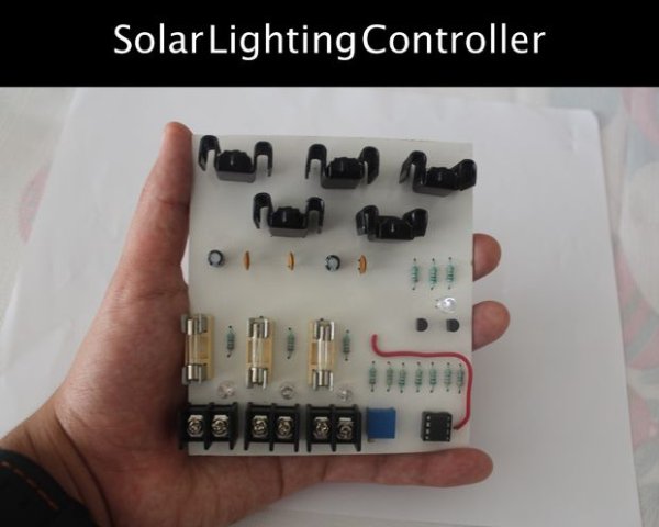
Materials
- 1-1K ¼ Watt Resistor
- 4-2,2K ¼ Watt Resistor
- 2-4,7K ¼ Watt Resistor
- 5- 10K ¼ Watt Resistor
- 1- 3,3K ¼ Watt Resistor
- 1-50K Trimming Potentiometer
- 3-100nF (0,1uF) Capacitors
- 2-22nF 25V Capacitors
- 2-MBR1660 Schottky Barrier Rectifier
- 4- Green LED Diodes
- 2-BC547 Transistors
- 2-IFR5305 MOSFET
- 1-PIC12F675 Microcontroller
- 1-7805 Voltage Regulator
- 1- 8 Pin Base
- 1- Aluminum Heatsink
- 5- Insulation Composite TO-220 with M3 Screw Insulation Cap TO-220
- 3- Terminal Wire Connectors
- 3-20mm PCB Fuse Holders
- 3-20mm 5 Amp Fuses
- 1- PCB Board (4.3” x 4.3”) or 2 830 Points Protoboard
- 5”- of Solid Core Wire (Red) for PCB Board or 4mts of Solid Core Wire for Protoboard (Black and Red, 4mts p/color)
- Couche Paper (1 or 2 sheets).
Tools:
- 1- Electric Wire Cutter
- 1- Electrical Pliers
- 1- Soldering Iron
- 1- Soldering Flux
- 1- Soldering Tin
- 1- Solder Sucker
- 1- PCB Drill
- 2- Screwdrivers (Plus and Plane)
- 1- Iron
- 1- Used Cloth
- 1- Plastic Recipient (for PCB Board)
- 1- Ferric chloride Acid for PCB
- Stainless Steel Scouring Pad
- Some Water
Software and Hardware:
- PICkit 2
- MikroC (Only if you want to modify some code)
- Microcontroller Programmer
Step 2: Circuit Diagram
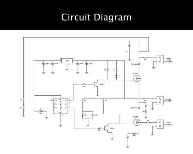
The very first step you need to do it’s look at the circuit diagram, this is the way you will connect your components to function properly. If you are using just a protoboard with some wires just peel some strings and connect. But if you are using a PCB Board go to the next step. I put some datasheets from the less common components to make it easy for you.
If you´ve decided to make a PCB Board follow this step, to get this complete, we need to do 5 things:
- The first thing is print the circuit, don’t worry I attached a PDF file with it, you must print it in a Couche sheet.
- The second thing is iron the circuit into the PCB Board, just put the Couche paper into the copper side of the PCB Board and adjust to fit properly, when you see that circuit’s tracks are sticking to the PCB Board correctly just stop ironing it and put the PCB Board in some water to clean the PCB Board.
- After cleaning the PCB Board, put some Ferric Chloride Acid into a plastic recipient with some water, and immerse PCB Board, Ferric Chloride Acid must cover all the surface of the board.
- When you only see the circuit’s tracks on the PCB Board remove it from Ferric Chloride Acid, clean the board with some water and sand it with a stainless-steel scouring pad
- Finally, you just have to drill the component´s holes.
For more detail: Low Cost Solar Lighting Controller
-
How does the controller operate?
The controller functions autonomously with no need to turn on or off the LED Light or press a button. -
What is the main microcontroller used?
The project uses the PIC12F675 microcontroller. -
Can I use a protoboard instead of a PCB?
Yes, you can use a 2 830 Points Protoboard or a 4.3" x 4.3" PCB Board. -
What software is required if I want to modify the code?
MikroC is needed only if you want to modify some code. -
Which tool is used to etch the PCB board?
Ferric chloride Acid is used to etch the circuit tracks on the PCB board. -
What type of rectifier is specified in the materials list?
The project requires 2-MBR1660 Schottky Barrier Rectifiers. -
How do you transfer the circuit design onto the PCB?
You print the circuit on Couche paper and iron it into the copper side of the PCB Board. -
What voltage regulator is included in the build?
A 1-7805 Voltage Regulator is used in the project.
