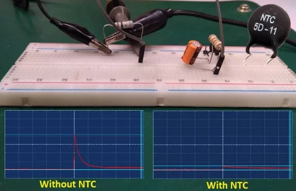
This is an article from the sequence of our articles in which we have been discussing about inrush current. We have already covered the basics of inrush current and the various types of Inrush Protection circuits in our previous articles. The most common method of inrush current protection is by using an NTC Thermistor, so in this article, we will discuss more on NTC Thermistor and how to use one to prevent Inrush current in your designs. This type of NTC Inrush Current Limiter circuit can be commonly found in power supply units like AC-DC Converters, or SMPS Circuits. Along with Inrush current protection, designers also include many other types of Protection circuits in their design; we have already covered various protection circuits, such as:
- Over Voltage Protection
- Over Current Protection
- Reverse Polarity Protection
- Short-circuit Protection
Simple Cost effective Inrush Current Protection Circuit
Although NTC is the widely used method to fight with inrush startup current that happens due to the high input capacitance of the load. A more conventional and straightforward method is to connect a fixed resistor in series between the load and input power supply. Let’s quickly go through this method to understand the drawbacks of this, which lead to the popularity of NTC. Consider the below image where a resistor is connected in series between the source power supply and the load.
The above circuit can be found in a low-cost SMPS or power supply module. This is a normal and cheapest way to deal with inrush current. As the resistor is used as the main component to control the input, it is acting as an inrush current limiter but this is not a proper way to connect a high current load with a power source. Why?
It is obvious that the resistor is blocking the inrush current but also resisting the normal current flow during the normal state of the circuit. Therefore, as the resistor value is fixed, the constant current flow through the resistor will dissipate the huge amount of power, thus, it will affect the overall efficiency of the circuit.
The worst part is if the load circuit consumes a huge amount of power the current flow through the resistor will increase, the power dissipation across this resistor will also increase, and the efficiency will eventually decrease. The more and more power it needs to be dissipated across the resistor, one needs a bigger wattage resistor to fulfill the power requirements. Not to mention, it is now clear that it is not a good choice to include a resistor as an inrush current limiter in a high power circuit.
But, what if a special type of resistor that could provide high resistance during the startup condition of the circuit and provide low resistance during the normal condition of the circuit, the efficiency will obviously increase and the power dissipation will be very minimal. This is exactly what an NTC does. NTC provides high resistance during the startup and low resistance during the normal state of the circuit.
How to use NTC for Inrush Current
As we discussed before, NTC is a special type of resistive component that provides high resistance during the startup condition but low resistance during the normal state of the circuit.
NTC stands for a negative temperature coefficient. It has a direct relationship between temperature and resistance. If the temperature increases slightly, the resistance decreases significantly. This is a useful feature to deal with limiting the inrush current. During the first power-up situation, when the load gets power from the power source for the very first time, the NTC acts as a high-value resistance in normal ambient temperature, thus effectively blocking inrush current into the circuit.
After a very short time, when the high current flows through the NTC, the internal temperature of the NTC increases slightly and ends up affecting the resistance. The resistance decreases significantly low and makes a direct path with the load and the power source. As the resistance is low during the normal working state, the power dissipation will be lower and the efficiency will improve also.
NTC Inrush Current Limiter Circuit
Generally, when the high-value capacitive load is connected with a power source, NTC is added between the positive lines of the power supply unit.
But in the case of an AC power supply unit or SMPS, the NTC is connected in the hotline before the bridge rectifier diode. We have already made a few SMPS or power supply circuit that uses NTC and inrush current limiter.
Selecting the right value of NTC
The calculation for selecting the inrush current limiter is to determine the peak voltage and the peak current. As NTC is a resistor, the Ohms law is sufficient to accommodate the value of the NTC resistance.
As per the ohm’s law, R = V/I and this is true for this case also. NTC resistance = Peak Voltage / Peak inrush current. For example, in 230V AC, the Vrms can be of 300V. At this Vrms, and to block 30A of peak inrush current 10 Ohms NTC is required.
Testing of NTC Inrush Current Limiter Circuit
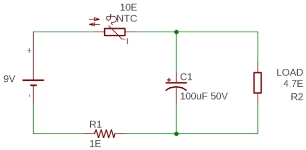
To evaluate the effect of the inrush current a capacitive load is connected across a power supply unit. The testing is done on a breadboard along with a 10 Ohms NTC. The circuit is shown in the below image.
The Resistor R1 is used as a shunt resistor to calculate the peak current. When the current flows through the resistor, a voltage drop will occur. An additional Oscilloscope is connected across this resistor to check the voltage drop across the resistor as shown below
The voltage drop can be determined using the Ohms’s law again where Current = Voltage / Resistance. In our case, we used 1 Ohms resistor, therefore, 1A of current flow through this resistor will produce a voltage drop of 1V. The NTC is connected across the positive line of the circuit.
The resistor R2 is a load resistor that issued for the fast discharging of the capacitor. The capacitor is a 100uF 50V general purpose capacitor. Since Inrush current flow happens very fast and for a short duration of time, the trigger function of the Oscilloscope is used.
After testing the circuit without the NTC, the peak current flow through the resistor is shown in the below image
As the oscilloscope is set to 1V per division, the peak voltage is 4.2V. Therefore, the peak current of 4.2A is recorded. This is the inrush current when a 9V power supply unit is connected across a 100uF 50V capacitor.
So, to block this, a 10 Ohms NTC is connected across the positive supply of the circuit. The output is shown in the below image –
The Oscilloscope setting was kept the same and also the source voltage is 9V as previous, but the inrush peak current is significantly decreased to almost 500mA.
In detail video of the inrush current effect with or without NTC can be seen in the below video. Therefore, by using an NTC, inrush current can effectively be suppressed across a huge capacitive load. If you have any questions please leave them in the comment section or use our forums for other technical questions.
Source: Inrush Current Limiting using NTC Thermistor


