


Summary of Infra-Red Panel Remote Control
This project is a custom-built circuit using a PIC12F615 microcontroller to control an Infra-Red heating panel via an existing electric fireplace remote. The system distinguishes between a short press and a long press (over 3 seconds) of the 'on' button to activate the panel, while a 'standby' press turns it off immediately. It includes a safety feature that automatically shuts down the panel after four hours and utilizes a hardware watchdog timer to reset the system if the software hangs, ensuring the power is cut in case of errors.Parts used in the IR Panel Remote Control:
- Breadboard
- PIC microcontroller 12F615TSOP48
- 38 Infra-Red receiver
- Fuse holder + fuse 4A/250V
- Ceramic capacitors: 2 * 100nF
- Resistors: 1 * 33k, 2 * 180 Ohm, 1 * 2k2
- LEDs: 1 Amber, 1 Green
- Diode 1N4148
- BC640 transistor
- Relays operating on +5 Volt
- 5 Volt Power supply
https://www.instructables.com/id/Remote-Controlled...
The biggest difference is that I did not only prototype this project but I actually build it to be used in my home.
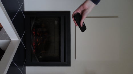
At home I have an electric fire place which has a heater on board. The problem with the heater is that it has a fan which makes a lot of noise. Since I like the fire place to generate some heat, I bought an Infra-Red Panel and mounted it above the fire place.
The electric fire place can be controlled via a Remote Control which uses the popular NEC protocol. The Remote Control has two buttons, ‘on’ and ‘standby’. My project was to use this Remote Control to control the Infra-Red Panel too. Of course I could create a circuit that switches it on when you press the ‘on’ button on the Remote Control but I do not always want to switch the panel on when I switch on the fire place.
What this circuit does is the following:
- When the ‘on’ button on the Remote Control is pressed for more than 3 seconds, it switches on the Infra-Red Panel
- When the ‘standby’ button on the Remote Control is pressed it switches off the Infra-Red Panel immediately
- If the Infra-Red Panel is switched on it will automatically be switched off after 4 hours. This is just a safety measure to prevent that the Panel stays on forever
- For safety reasons the circuit uses the on-board watchdog of the PIC. If for some reason the program hangs, the circuit will be reset and the Infra-Red Panel will be switched off
As always I used a PIC microcontroller and created all software without using any specific libraries. Arduino fans can use of course do the same or use the libraries that are available for e.g. the Remote Control decoding part.
Step 1: Required Components
You need to have the following components for this project:
- A piece of breadboard
- PIC microcontroller 12F615
- TSOP4838 Infra-Red receiver
- Fuse holder + fuse 4A/250V
- Ceramic capacitors: 2 * 100nF
- Resistors: 1 * 33k, 2 * 180 Ohm, 1 * 2k2
- LED: 1 Amber, 1 Green
- Diode 1N4148
- BC640 transistor
- Relays operating on +5 Volt and capable of switch sufficient mains power. I used: https://www.aliexpress.com/item/5pcs-SRD-05VDC-SL...
- 5 Volt Power supply sufficient to power the circuit. I used: https://www.aliexpress.com/item/5V-700mA-3-5W-AC-...
See the schematic diagram for how the components are connected.
Attachments
Step 2: Building the Electronics
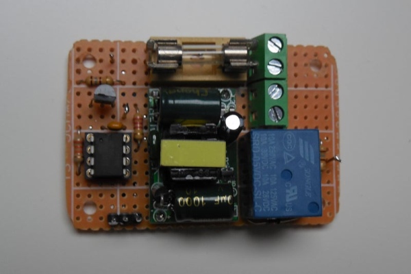
You can build the circuit on a breadboard but be very careful with the Fuse and the Relays that switch the mains power for the Infra-Red Panel. Do not touch the mains power in any way!
In the pictures you can see the circuit as I build it on the breadboard. I needed to put it in a housing but since this housing is not visible – the whole circuit is placed behind the electronic fire place – I made it of MDF. The Infra-Red sensor and the ‘On’ LED are connected to a cable and are mounted with some tape under and at the front of electric fire place.
I did not measure it exactly but the circuit draws about 90 mA when the relays is switched on. The relay is the component that draws most of the current, about 55 mA. The power supply used can easily provide the required power for this circuit.
Step 3: The Software
As already mentioned, the software is written for a PIC12F615. It was written in JAL. Since I did not use any specific libraries the total code size is 626 bytes which fits nicely in the 1k program flash memory this specific controller has.
The software performs the following main tasks:
- Decoding the Remote Control messages. For this it uses a capture timer that captures the duration of the bits. The decoding routine works completely interrupt based and uses each bit level change of the RC message by constantly changing the interrupt edge level. This increases the reliability of the decoding routine.
- Switch on the relays when the ‘on’ command is received for more than 3 seconds. Note that the NEC protocol only sends a command once after which it sends repeat messages. The program waits for the ‘on’ command and then counts the number of repeat messages that have to be received within a certain time frame
- Switch off the relay when the ‘standby’ command is received
- Switch off the relay after being on for 4 hours
- Kicking the watch dog on a frequent basis. The watchdog will not reset the controller if it is triggered each 18 ms. The main program uses a loop time of 1 ms in which it kicks the watchdog and so prevents the dog from barking.
The PIC controller runs on an internal clock with a frequency of 8 MHz. The Intel Hex file and the JAL source files are attached.
Have fun building your own project and looking forward to your reactions.
Attachments
Source: Infra-Red Panel Remote Control
Quick Solutions to Questions related to IR Panel Remote Control:
- How does the system turn on the Infra-Red Panel?
The panel switches on when the on button on the remote control is pressed for more than 3 seconds. - How do you switch off the Infra-Red Panel?
Pressing the standby button on the remote control switches off the panel immediately. - Does the panel stay on forever?
No, the panel will automatically be switched off after 4 hours as a safety measure. - What happens if the program hangs?
The on-board watchdog resets the circuit, which switches the Infra-Red Panel off. - Which microcontroller is used in this project?
The project uses a PIC12F615 microcontroller running at an internal clock frequency of 8 MHz. - Can Arduino users use libraries for this project?
Yes, Arduino fans can use available libraries for parts like the remote control decoding. - What programming language was used for the software?
The software was written in JAL without using any specific libraries. - How does the remote control decoding work?
It uses a capture timer and interrupt-based routines that constantly change the interrupt edge level for reliability.
Related projects
Voice Activated Power Sockets (Home Automation)
Yet another voice controlled home automation system! As shown in the picture, the system can control any electrical appliance, by turning ON...
Home Automation & SecurityHome Security System with GSM Using 8051 Microcontroller
Security is a big challenge everywhere because thefts are increasing day by day owing to the unsafe and insecure security systems in...
Home Automation & SecurityHome Automation and Security System using Microcontroller ATMEGA8 with Arduino Programming
Home automation and security systems have become very popular these days, today industrial automation techniques are widely adopted by luxurious homes and...
Home Automation & Security · PIC16F84ABicycle Persistence of Vision Light Display using PIC16F84
In February of 2007 I spent a little while prototyping a board that turns any bicycle wheel into a moving display billboard...
Home Automation & SecurityFTS-8 subtone encoder
Many Yaesu transceivers from the 1990s and thereabouts could use an optional FTS-8 module, that provided subtone generation for transmission, and subtone...
Home Automation & SecurityHand Sign Lock
Introduction Security using technology is a growing and expanding field to protect against the user's identity or property. As more advanced tools...

Muhammad Bilal
I am a highly skilled and motivated individual with a Master's degree in Computer Science. I have extensive experience in technical writing and a deep understanding of SEO practices.