
I’m completely new to the world of PIC Microcontrollers and electrical engineering so please go easy
Anyway, I managed to program my PIC 16f627 to turn on three LEDs when push button (trigger button) is pressed and start a shut down sequence (basically each LED toggles off one after another with a 5 second delay in between) when another pushbutton is pressed (reset button). I’ve been testing this on a Velleman’s K8048 PIC Programmer/ Experimentation board.  PINs RA0 and RA2 are the inputs for the trigger and reset pushbuttons respectively while pins RB0, RB1, and RB2 are the output pins for the LEDs.
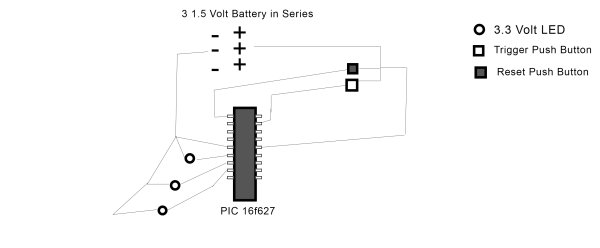
Working with the experimentation board is great but I want to move this to an actual circuit. The problem is I have no idea where to start. I’ve bought 3 LEDs (3.3 Volts each), some pushbuttons, and wire and I’ve constructed the following circuit:
(sorry for the horrendous schematic)
In the circuit I constructed, I first tested to see if the LEDs would work with 3 1.5 Volt AA batteries and they worked fine so I figured resisters wouldn’t be necessary.
This does not work, however, and I’m totally lost. For reference, here is my code for the PIC. Its written in C using MikroC. It works on the experimentation board so I don’t think its a problemvoid main() {
TRISB.RB0 = 0;
TRISB.RB1 = 0;
TRISB.RB2 = 0;
PORTB.RB0 = 0;
PORTB.RB1 = 0;
PORTB.RB2 = 0;
CMCON = 0x07;
TRISA = 255;
for(;;){
if(PORTA.RA0 == 1 && PORTB.RB0 == 1 && PORTB.RB1
== 1 && PORTB.RB2 == 1){
delay_ms(5000);
PORTB.RB0 = 0;
delay_ms(5000);
PORTB.RB1 = 0;
delay_ms(5000);
PORTB.RB2 = 0;
}
if(PORTA.RA2 == 1){
PORTB.RB0 = 1;
PORTB.RB1 = 1;
PORTB.RB2 = 1;
}
}
}
For more detail: How to Wire a PIC Microcontroller?
