Summary of Generating PWM signals on GPIO pins of PIC Microcontroller
This article explains how to generate PWM signals on PIC16F877A GPIO pins using Timer interrupts instead of CCP modules, enabling control of multiple servos. It details the mathematical formulas for calculating duty cycle and frequency, provides C code for configuring Timer0 and ADC, and demonstrates a simulation in Proteus with a potentiometer and servo motor.
Parts used in the Robotic Arm Project:
- PIC16F877A Microcontroller
- 20MHz Crystal Oscillator
- Potentiometer (connected to AN0)
- Servo Motor (connected to RD1)
- 7805 Voltage Regulator
- Digital Oscilloscope (for simulation)
- Proteus Simulation Software
PWM signal generation is a vital tool in every embedded engineers arsenal, they come in very handy for lot of applications like controlling the position of servo motor, switching few power electronic ICs in converters/invertors and even for a simple LED brightness control. In PIC microcontrollers PWM signals can be generated using the Compare, Capture and PWM (CCP) modules by setting the required Registers, we have already learnt how to do that in the PIC PWM tutorial. But there is one considerable drawback with that method.
The PIC16F877A can generate PWM signals only on pins RC1 and RC2, if we use the CCP modules. But we might encounter situations, where we need more pins to have PWM functionality. For instance in my case, I want to control 6 RC servo motors for my robotic arm project for which the CCP module is hopeless. In these scenarios we can program the GPIO pins to produce PWM signals using timer modules. This way we can generate as many PWM signals with any required pin. There are also other hardware hacks like using a multiplexer IC, but why invest on hardware when the same can be achieved though programming. So in this tutorial we will learn how to convert a PIC GPIO pin into a PWM pin and to test it we will simulate it on proteus with digital oscilloscope and also control the position of Servo motor using the PWM signal and vary its duty cycle by varying a potentiometer.
What is a PWM Signal?
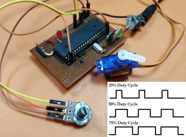
Before we get into the details, let us brush up a bit on what PWM Signals are. Pulse Width Modulation (PWM) is a digital signal which is most commonly used in control circuitry. This signal is set high (5v) and low (0v) in a predefined time and speed. The time during which the signal stays high is called the “on time” and the time during which the signal stays low is called the “off time”. There are two important parameters for a PWM as discussed below:
Duty cycle of the PWM
The percentage of time in which the PWM signal remains HIGH (on time) is called as duty cycle. If the signal is always ON it is in 100% duty cycle and if it is always off it is 0% duty cycle.
Duty Cycle =Turn ON time/ (Turn ON time + Turn OFF time)
Frequency of a PWM
The frequency of a PWM signal determines how fast a PWM completes one period. One Period is complete ON and OFF of a PWM signal as shown in the above figure. In our tutorial we will set a frequency of 5KHz.
Calculating Duty Cycle for PWM
To generate PWM signal on a GPIO pin we have to simply turn it on and off for a pre-defined time. But it is not as simple as it sounds. This on time and off time should be accurate for every cycle so we simply cannot use delay functions, hence we employ a timer module and use the timer interrupts. Also we have to consider the duty cycle and the frequency of the PWM signal that we generate. The following variable names are used in program to define the parameters.
|
Variable Name |
Refers to |
|
PWM_Frequency |
Frequency of the PWM Signal |
|
T_TOTAL |
Total time taken for one complete cycle of PWM |
|
T_ON |
On time of the PWM signal |
|
T_OFF |
Off time of the PWM signal |
|
Duty_cycle |
Duty cycle of the PWM signal |
So now, let’s do the math.
This is the standard formulae where frequency is simply the reciprocal of time. The value of frequency has to be decided and set by the user based on his/her application requirement.
T_TOTAL = (1/PWM_Frequency)
When the user changes the Duty cycle value, our program should automatically adjust the T_ON time and T_OFF time according to that. So the above formulae can be used to calculate T_ON based on the value of Duty_Cycle and T_TOTAL.
T_ON = (Duty_Cycle*T_TOTAL)/100
Since the Total time of the PWM signal for one full cycle will be the sum of on time and off time. We can calculate the off time T_OFF as shown above.
T_OFF = T_TOTAL – T_ON
With these formulae in mind we can begin programming the PIC microcontroller. The program involves the PIC Timer Module and PIC ADC Module to create a PWM signal based with a varying Duty cycle according to the ADC value form the POT. If you are new to using these modules then it is strongly recommended to read the appropriate tutorial by clicking on the hyperlinks.
Programming PIC to generate PWM on GPIO Pins
The complete program for this tutorial can be found at the bottom of the website like always. In this section let’s understand how the program is actually written. Like all programs, we begin by setting the configurations bits. I have used the memory views option to set it for me.
// CONFIG
#pragma config FOSC = HS        // Oscillator Selection bits (HS oscillator)
#pragma config WDTE = OFF       // Watchdog Timer Enable bit (WDT disabled)
#pragma config PWRTE = OFF      // Power-up Timer Enable bit (PWRT disabled)
#pragma config BOREN = ON       // Brown-out Reset Enable bit (BOR enabled)
#pragma config LVP = OFF        // Low-Voltage (Single-Supply) In-Circuit Serial Programming Enable bit (RB3 is digital I/O, HV on MCLR must be used for programming)
#pragma config CPD = OFF        // Data EEPROM Memory Code Protection bit (Data EEPROM code protection off)
#pragma config WRT = OFF        // Flash Program Memory Write Enable bits (Write protection off; all program memory may be written to by EECON control)
#pragma config CP = OFF         // Flash Program Memory Code Protection bit (Code protection off)

// #pragma config statements should precede project file includes.
// Use project enums instead of #define for ON and OFF.

#include <xc.h>
Then we mention the clock frequency used in the hardware, here my hardware uses 20MHz crystal, you can enter the value based in your hardware. Followed by that is the frequency value of the PWM signal. Since my aim here it to control a hobby RC servo motor which requires a PWM frequency of 50Hz I have set 0.05KHz as the Frequency value you can also change this based in your application requirements.
#define _XTAL_FREQ 20000000
#define PWM_Frequency 0.05 // in KHz (50Hz)
Now, that we have the value of Frequency we can calculate the T_TOTAL using the above discussed formulas. The result is dived by 10 to get the value of time in milli seconds. In my case the value of T_TOTAL will be 2 milli seconds.
int T_TOTAL = (1/PWM_Frequency)/10; //calculate Total Time from frequency (in milli sec)) //2msec
Followed by that, we initialize the ADC modules for reading the position of the Potentiometer as discussed in our ADC PIC tutorial. Next we have the Interrupt service routine which will be called every time, the timer overflows we will get back to this later, for now let’s check the main function.
Inside the main function we configure the timer module. Here I have configured the Timer module to overflow for every 0.1ms. The value for the time can be calculated by using the formulae below
RegValue = 256-((Delay * Fosc)/(Prescalar*4)) delay in sec and Fosc in hz
In my case for a delay of 0.0001 seconds (0.1ms) with prescalar of 64 and Fosc of 20MHz the value of my register (TMR0) should be 248. So the configuration looks like this
/*****Port Configuration for Timer ******/
    OPTION_REG = 0b00000101;  // Timer0 with external freq and 64 as prescalar // Also Enables PULL UPs
    TMR0=248;       // Load the time value for 0.0001s; delayValue can be between 0-256 only
    TMR0IE=1;       //Enable timer interrupt bit in PIE1 register
    GIE=1;          //Enable Global Interrupt
    PEIE=1;         //Enable the Peripheral Interrupt
    /***********______***********/
Then we have to set the Input and Output configuration. Here we are using the AN0 pin for reading the ADC value and PORTD pins to output the PWM signals. So initiate them as output pins and make them low by using the below lines of code.
    /*****Port Configuration for I/O ******/
    TRISD = 0x00; //Instruct the MCU that all pins on PORT D are output
    PORTD=0x00; //Initialize all pins to 0
    /***********______***********/
Inside the infinite while loop, we have to calculate the value of on time (T_ON) from the duty cycle. The on time and duty cycle varies based on the position of the POT so we do it repeatedly inside the while loop as shown below. 0.0976 is the value that has to be multiplied with 1024 to get 100 and to calculate T_ON we have multiplied it with 10 to get value in milli seconds.
while(1)
    {
       POT_val = (ADC_Read(0)); //Read the value of POT using ADC

       Duty_cycle = (POT_val * 0.0976); //Map 0 to 1024 to 0 to 100

       T_ON = ((Duty_cycle * T_TOTAL)*10 / 100); //Calculate On Time using formulae unit in milli seconds

       __delay_ms(100);
    }
Since the timer is set to over flow for every 0.1ms, the timer interrupt service routine ISR will be called for every 0.1ms. Inside the service routine we use a variable called count and increment it for every 0.1ms. This way we can keep track f time. To learn more about Interrupts in PIC microcontroller, follow the links
    if(TMR0IF==1) // Timer flag has been triggered due to timer overflow -> set to overflow for every 0.1ms
    {
        TMR0 = 248;     //Load the timer Value
        TMR0IF=0;       // Clear timer interrupt flag
        count++; //Count increments for every 0.1ms -> count/10 will give value of count in ms
    }
Finally it is time to toggle the GPIO pin based on the value of T_ON and T_OFF. We have the count variable that keeps track of time in milli seconds. So we use that variable to check if time is less than on time, if yes then we keep the GPIO pin turned on else we turn it off and keep it turned off until the new cycle starts. This can be done by comparing it to the total time of one PWM cycle. The code to do the same is shown below
if (count <= (T_ON) ) //If time less than on time
        RD1=1; //Turn on GPIO
    else
        RD1=0; //Else turn off GPIO

    if (count >= (T_TOTAL*10) ) //Keep it turned off until a new cycle starts
        count=0;
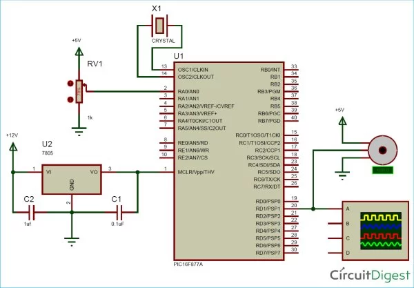
Circuit Diagram
The circuit diagram for generating PWM with GPIO pin of PIC microcontroller is really simple, just power the PIC with oscillator and connect the potentiometer to pin AN0 and Servo Motor to pin RD1, we can use GPIO pin to get the PWM signal, I have selected RD1 just out of random. Both the Potentiometer and the Servo motor is powered by 5V which is regulated from the 7805 as shown below in the circuit diagram.
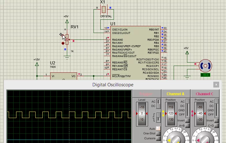
Simulation
To simulate the project I used my proteus software. Build the circuit shown below and link the code to your simulation and run it. You should get a PWM signal on the RD1 GPIO pin as per our program and the duty cycle of the PWM should get controlled based on the position of the potentiometer. The below GIF shows how the PWM signal and servo motor respond when the ADC value is changed through the potentiometer.
Read more Detail:Generating PWM signals on GPIO pins of PIC Microcontroller
- Why use GPIO pins instead of CCP modules for PWM?
The CCP module is limited to specific pins like RC1 and RC2, whereas programming GPIO pins allows generating as many PWM signals as needed. - How is the total time for one PWM cycle calculated?
T_TOTAL is calculated by dividing 1 by the PWM Frequency value. - What formula determines the On Time for the signal?
T_ON is calculated by multiplying the Duty Cycle by T_TOTAL and then dividing by 100. - Which timer module is employed to ensure accurate timing?
The Timer0 module is used with interrupts to track time accurately without relying on delay functions. - What frequency was set for controlling the hobby RC servo motor?
A frequency of 50Hz (0.05KHz) was selected for the servo motor application. - How is the duty cycle value derived from the potentiometer?
The ADC reads the potentiometer position (0-1024), which is multiplied by 0.0976 to map it to a 0-100 duty cycle percentage. - What register value loads the timer for a 0.1ms overflow?
The value 248 is loaded into the TMR0 register to achieve a 0.1ms delay with a 20MHz clock and 64 prescaler. - Which pin was used to output the PWM signal in this tutorial?
Pin RD1 was randomly selected to output the generated PWM signal.