Summary of Designing a Door Access Control System with Programmed AT89C52 Microcontroller
Summary: An AT89C52 microcontroller-based dual-factor access door control system integrates smartcard and password authentication to improve hygiene and accessibility over biometric methods. Using UML for system modeling, hardware includes keypad, display, smartcard reader, relay driver, DC motor, and power supply. A 555-timer-based smartcard provides a high output signal to port 0 for identification; assembly language (ASEM-51) programs the controller to verify PINs and drive a motor to open/close the door. PCB layout and prototyping were performed with CAD tools and UV stenciling.
Parts used in the Access Door Control System:
- AT89C52 microcontroller
- Power supply (regulated 5V with 230V AC input)
- Matrix keypad (4x3)
- Display unit (six 7-segment common anode LEDs)
- Smartcard (vero-board with 555 timer monostable)
- Smartcard reader (RAM card slot interfaced to Port 0)
- Relay driver
- 12V DC motor
- Motor driver interface (controlled via P2.6 and P2.7)
- Printed circuit board (PCB) and CAD/Proteus ARES layout tools
- Assembler/IDE (ASEM-51) for AT89C52 programming
Abstract:
Biometric door systems present limitations as they are unsuitable for widespread use due to hygiene concerns and accessibility issues for individuals with physical disabilities. To address these challenges, a novel approach was devised utilizing an AT89C52 microcontroller-based access door control system, integrating dual-factor authentication via password and smartcard. Unified Modeling Language was employed to depict the system’s functionality, encompassing hardware components such as the microcontroller, power supply, keypad, display unit, smartcard reader, relay driver, and DC motor. The card reader interface was designed with a RAM card slot connected to port 0 of the microcontroller. Programming for the AT89C52 system was accomplished using assembly language within an integrated development environment, ensuring seamless operation. Through systematic integration of software modules within a main control loop, the system effectively mitigates unauthorized access attempts to secure areas, fulfilling its intended purpose.
I. INTRODUCTION
The implementation of an access control system stands as a significant achievement, continuously enhancing global security for both lives and property. Such a system is designed to grant entry solely to authorized individuals while preventing unauthorized access. The critical necessity for a robust access control system cannot be overstated, particularly in contrast to traditional key locks which offer no restrictions once a key falls into unauthorized hands.
A door, typically composed of sturdy, movable materials such as wood, metal, or glass, serves as a barrier at building entrances or within rooms. It functions to impede unauthorized entry and can also be employed for aesthetic or spatial segregation purposes. Doors are essential elements in ensuring privacy, security, and convenience within interior spaces.
The introduction and widespread adoption of automatic door systems, pioneered by supermarkets in the United States, aimed to alleviate the inconvenience faced by shoppers. However, such systems posed a security vulnerability by granting access indiscriminately to both authorized and unauthorized individuals due to their lack of authentication mechanisms.
Smart cards, featuring embedded microprocessor chips, have revolutionized authentication and authorization processes. This technology significantly enhances card security and finds widespread applications across various sectors. In banking, microchip-enabled cards authenticate transactions, safeguarding users and institutions against fraudulent activities. Similarly, in healthcare, smart cards securely store extensive patient data, facilitating communication with insurers and medical professionals.
E-passports utilize smart card technology to store digital versions of identity card information, enhancing security and authentication processes. In information technology, smart cards play a crucial role in securing user logins, encrypting sensitive data, and managing digital certificates. Additionally, in mobile technology, smart cards ensure the security of value-added services, while electronic purses utilize them to store monetary value for small transactions, facilitating secure purchases.
II. LITERATURE REVIEW
According to Okner (2021), a conventional configuration for access control involves an access controller responsible for decision-making, lock and unlock scheduling, and various authentication and authorization tasks at entry points. This setup constitutes an access control system employing multi-factor user authentication, combining possession-based and knowledge-based authentication methods to serve as a vigilant security measure.
Lal et al. (2016) emphasized that the primary determinant for granting access is the verification of identity, a task only achievable by the authorized user. The access controller, functioning as the central processing unit, is constructed with AT89C52 and operates by scrutinizing information provided at the entry terminal through assembly language programming of the microcontroller. Authentication is executed through a binary decision process, wherein the system determines whether access should be granted or denied based on a YES or NO outcome. Identity validation employs a dual-factor authentication approach, combining possession of a smart card with knowledge of a password to gain entry.
Khan and Dristy (2015) developed an android-based security and home automation system utilizing a PIC microcontroller to ensure security at the home’s main entrance and to manage functions such as car door locks and household appliances.
Amunullah (2013) engineered a reprogrammable digital door lock security system reliant on a matrix keypad and GSM/CDMA network. Valid entry through the keypad or authorized phone call triggers door unlocking, with an Instant Power Supply (IPS) circuit ensuring functionality during power outages. Despite its use of a predefined mobile number and lack of mobility authentication, a more secure and remotely manageable solution is deemed necessary.
Ajay, Shelja, and Swati (2014) devised a sensor-based home automation security system incorporating a GSM module and shock sensor to detect intruders. Upon detection, the system activates a door locking mechanism and sends SMS alerts to occupants.
Jain et al. (2016) designed a password-protected home automation system featuring an automatic door lock controlled by an Arduino Uno microcontroller. Access to the system’s functionalities, including door, light, and fan control, is granted upon successful password authentication.
Akubue (2016) developed a door control system integrating a smart card reader and interactive code lock, driven by an AT89C51 microcontroller programmed in Visual Basic. The system automatically closes the door after 30 seconds of inactivity, although an extended waiting period before keypad and display deactivation is suggested.
Lee et al. (2017) implemented an advanced smartcard-based password authentication system fortified with extended chaotic maps to withstand denial-of-service and insider attacks.
Gupta et al. (2019) proposed a smartcard solution for vehicular information management, consolidating essential vehicle data onto a single card to streamline documentation and support government initiatives with unique serial number identification.
Mcs-51 Assembly programming
According to Visa and Asogwa (2012), the Intel AT89C52 microcontroller represents a self-contained computing unit condensed onto a single chip. Intel pioneered the development of the first 8-bit microcontroller in 1976, followed by an enhanced 16-bit version introduced in 1982. In the realm of microcontrollers, programming entails crafting a structured sequence of instructions to be executed by the processor in a specific order, aiming to accomplish a predetermined task. This process involves debugging, troubleshooting, and organizing instructions to ensure the desired functionality.
Programming languages, as outlined by Keil (1995), adhere to specific vocabularies, grammatical rules, and syntactic conventions. Microcontrollers operate with three tiers of programming languages: machine language, assembly language, and high-level languages.
Alu (2021) delineated machine language as code composed of binary bit patterns, represented by combinations of 1s and 0s, which are stored as varying voltage levels. This fundamental programming language constitutes the lowest level of comprehension for microcontrollers.
Assembly Language serves as a human-readable representation of machine language, employing English-like mnemonics and hexadecimal codes. Assembly language programs, composed of mnemonic instructions, can be directly translated into machine-understandable formats with the aid of an assembler—a software tool dedicated to this conversion task.
Assembly language programming necessitates a comprehensive understanding of microcontroller architecture. ASEM-51 assembly language, for instance, aligns with the Intel standard, ensuring compatibility with existing assembler sources for MCS-51-based microcontroller projects.
High-level languages utilize human-readable words and statements, abstracting away microcontroller architecture intricacies. Compilers translate programs written in high-level languages into machine code. Examples of high-level languages include BASIC, C-Pascal, C++, and Java. Despite the convenience of high-level languages, assembly language programming offers advantages such as faster execution of instructions and reduced memory usage. Additionally, assembly language assemblers are reliable, compact, and well-documented, offering features like Intel Hex file output generation, automatic code optimization, and easy testing on MCS-51 target boards.
III. METHODOLOGY
System Modeling
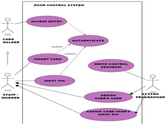
System modeling involves utilizing models to conceptualize, construct, and demonstrate the interactions of processes within a functional system. The use case diagram, depicted in Figure 1, serves as a dynamic or behavioral representation in the Unified Modeling Language (UML), illustrating the functionality of the system. Typically, the system is developed, designed, or operated, while the actors, representing individuals or entities, assume defined roles within the system. In the context of this study, the system pertains to access door control, with the actors comprising the card holder and system programmer.
Activity diagram of the system
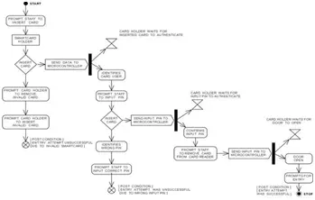
An activity diagram holds significant importance within the Unified Modeling Language (UML), serving to illustrate the dynamic elements of a system. It depicts the transition of activities from one state to another, effectively showcasing the flow of operations within the system. This diagram effectively outlines the sequence of actions performed, commencing from initiation to conclusion, as depicted in Figure 2.
Hardware Design
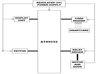
The hardware setup consists of an AT89C52 microcontroller, power supply unit, keypad, display module, smartcard, smartcard reader, relay driver, and a DC motor, as illustrated in Figure 3.
Smartcard Design
The design incorporates an extended contact smartcard interface, utilizing a 555 timer integrated circuit affixed to a rectangular vero-board to function as the card chip. The 555 timer is set up in a one-shot mono-stable multivibrator configuration, generating a high state through its output trigger (pin 3), as depicted in Figure 4.
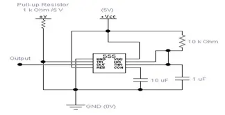
Once activated, the 555 monostable circuit will maintain its elevated output state until disengaged from the card reader. The output pin possesses the capability to drive any TTL circuit, with the ability to source or sink up to 200mA of current at an output voltage of approximately 1.5V. This level of output is sufficient to operate other logic ICs, LEDs, or small lamps. Given these specifications, direct connection of the microcontroller to the output is feasible and practical. When the smartcard is inserted into the card reader, the 555 timer on the card is powered through PIN 8 (VCC) and PIN 1 (GND).
Smartcard Reader Design
The card reader, integrated with a Random Access Memory (RAM) card reader slot within the computer’s Central Processing Unit (CPU), interfaces with port 0 of the AT89C52 microcontroller. The slot is designed to accommodate the thickness of the vero-board, with its pinouts connected directly to port 0 of the microcontroller. Upon insertion of a smartcard into the reader, the output pin 3 sends a high state signal through the card reader to port 0 of the microcontroller for authentication. The data received by port 0 serves to identify the card user and dictates the subsequent operations programmed into the microcontroller.
AT89C52 Microcontroller
The microcontroller utilized in this context is the AT89C52, renowned for its low power consumption and high-performance characteristics. It features 8 kilobytes of Flash Erasable and Programmable Read-Only Memory (EPROM) with non-volatile memory technology. The integrated flash memory enables reprogramming of the program memory either within the system or via a conventional non-volatile memory programmer. The Atmel AT89C52, depicted in Figure 5, amalgamates a versatile 8-bit CPU with flash memory on a single chip, presenting a robust microcomputer solution that offers flexibility and cost-effectiveness for a multitude of embedded control applications.
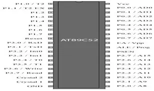
The AT89C52 offers a range of standard features, including 8k bytes of flash memory, 256 bytes of RAM, 32 I/O lines, three 16-bit timer/counters, a six-vector two-level interrupt structure, a full-duplex serial port, an on-chip oscillator, and clock circuitry.
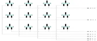
Matrix Keypad
A matrix keypad is composed of an array of push buttons arranged in rows and columns, with the microcontroller’s input/output (I/O) pins linked to the rows and columns of the matrix. Each row of push buttons is connected to a single pin of the microcontroller, while each column of push buttons is connected to another pin. In this particular setup, a 3×4 matrix keypad configuration is utilized, as depicted in Figure 6.
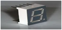
Display unit
The display screen consists of a serially arranged array of six (6) LED displays with common anode configuration. A seven-segment display is a highly efficient type of display utilized in electronic devices to represent decimal numbers from 0 to 9, as well as alphabets and basic characters. This type of display finds application in various electronic devices such as microwave ovens, calculators, washing machines, radios, microcontroller projects, and digital clocks. Each seven-segment display comprises eight (8) LEDs, individually labeled as a, b, c, d, e, f, g, and Dp, with the Dp pin and the other pins serving as the common pin. The design employs a common anode configuration, as illustrated in Figure 7.
Working principles of the system
The hardware design incorporates a power supply circuit linked to a 230V AC power source. A regulated power supply, maintaining a consistent 5V output, is employed to power various components including the AT89C52 microcontroller, keypad, relay driver, and display unit within the system. The display unit serves to guide users, prompting them to insert their card into the reader for authentication purposes.
Upon initiation of the written program, the microcontroller initiates scanning of the smartcard reader via port 0. When a card is inserted, it establishes physical contact with the 5V supply, thereby activating a monostable circuit embedded within it.
The persistent presence of a stable high output logic 1 initiates the setting of the bit in port 0 of the microcontroller. Guided by the programmed instructions, the microcontroller discerns the card user’s identity and prompts them to input a confidential PIN for authentication. Preceding the keypad’s push button scan, the microcontroller dispatches #0FFH to port 3. Upon detection of a push on button 1, logic 1 is reset in P3.0 and P3.3, transitioning them to logic 0. In accordance with the program’s directives, the microcontroller transmits data #1 (represented as decimal number 1) to the display unit. This process is applicable for numeric values ranging from 0 to 9.
Once the four-digit PIN is inputted into the display unit, the cardholder is prompted to activate the enter button. Pressing the enter button transitions logic 1 in P3.2 and P3.6 to logic 0. With these two bits set to logic 0, the microcontroller proceeds to authenticate by cross-referencing the four secret data displayed with the information stored within the microcontroller. In cases where discrepancies are detected, the microcontroller communicates to the display unit indicating “ACCESS DENIED.” Conversely, if the four secret data match, the microcontroller transmits a message to the display unit prompting “PLEASE ENTER.” Additionally, the microcontroller sets the logic of P2.6 to 1 and P2.7 to 0. Leveraging P2.6 and P2.7, the microcontroller interfaces with the motor driver, regulating the connection of the two terminals to the positive (+ve) and negative (-ve) terminals of the 12V DC motor. A pre-defined program controls the motor’s rotation, facilitating both clockwise and anti-clockwise movements, corresponding to the opening and closing actions of the door.
IV. DISCUSSION OF RESULTS
In order to attain favorable outcomes, direct interfacing of the AT89C52 microcontroller with the keypad was established, enabling input access through software coding for button press encoding and decoding. The keypad’s three-row terminals were linked to P3.0 – P3.2 of the microcontroller, while its four-column terminals were connected to P3.3 – P3.6. Utilizing a software tool, the subsystem’s constituent elements were meticulously integrated and simulated prior to physical assembly. To streamline the process and mitigate circuitry discrepancies, the finalized circuitry was exported to another Computer-Aided Design (CAD) software tool, specifically Proteus ARES. This software facilitated the generation of interconnected lines between pins, ensuring accurate depiction of the circuit layout. The CAD tool also provided functionality for arranging components on the board and defining their respective positions before establishing connections via traces.
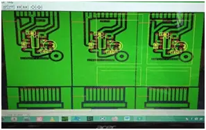
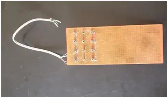
A printed PCB layout mesh was created by stretching it across a wooden frame, as illustrated in Figure 10. Utilizing the direct stenciling technique, an emulsion sensitized with ammonium dichromate solution, which reacts to ultraviolet (UV) light exposure, was applied onto the mesh. After coating the mesh, the emulsion was dried using a heater and shielded from light in a darkened environment to form a screen. Subsequently, the screen was exposed to ultraviolet (UV) light for approximately 20-35 seconds, with the printed PCB film securely held against it, resulting in the creation of a stencil.
This process entails transferring the PCB layout onto the screen, generating a negative stencil on the PCB print-out, which is then employed to imprint the PCB layout onto the copper-clad board using ink. Prior to this, the copper-clad board is meticulously cleansed with fine sandpaper to eliminate any copper oxide residue deposited on the surface.

The software application for the customizable AT89C52 access door control system was coded using assembly language. The source code was crafted within an Integrated Development Environment (IDE), incorporating the typical syntax of assembler statements, assembler instructions, and various controls pivotal in shaping the assembler process and facilitating hex file generation, all managed through ASEM-51.
- What microcontroller is used in the system?
The AT89C52 microcontroller is used. - How does the smartcard signal the microcontroller?
The smartcard uses a 555 timer monostable whose output goes high when inserted and connects to port 0 of the microcontroller. - Can the system use dual-factor authentication?
Yes, it uses dual-factor authentication combining smartcard possession and a PIN password. - What language is used to program the AT89C52?
Assembly language (ASEM-51) is used to program the AT89C52. - How is the keypad connected to the microcontroller?
The 4x3 matrix keypad rows are connected to P3.0–P3.2 and columns to P3.3–P3.6 of the microcontroller. - What drives the door motor to open and close?
The microcontroller sets P2.6 and P2.7 to control the motor driver, switching the 12V DC motor for clockwise and anticlockwise rotation. - What display type is used to prompt users?
A serial array of six common-anode seven-segment LED displays is used to guide users. - How is the smartcard reader interfaced physically?
The RAM card reader slot accepts the vero-board card and its pinouts are connected directly to port 0 of the AT89C52. - What power supply voltages are used in the system?
A regulated 5V supply powers the microcontroller and peripherals, and a 12V supply powers the DC motor; the system is fed from 230V AC.