Summary of automatic power factor controller using microcontroller
This article describes an Automatic Power Factor Controller using a PIC 16F877A microcontroller. The system steps down 230V AC voltage and extracts current waveforms via transformers. Zero-crossing detectors built with LM358 op-amps feed signals to the microcontroller, which calculates the power factor by analyzing time differences between voltage and current zero crossings. If the power factor drops below 0.9, the microcontroller activates relays via a ULN2003 driver IC to connect parallel capacitors, correcting the phase difference. An LCD display shows the real-time power factor value.
Parts used in the Automatic Power Factor Controller:
- 230 V, 50 Hz Voltage Transformer
- Current Transformer
- LM358 Op-Amp (Voltage Comparators)
- PIC 16F877A Microcontroller
- 16–2 LCD Display
- Relays
- ULN2003 Driver IC
- Darlington Pairs (internal to ULN2003)
- Power Factor Correcting Capacitor
The 230 V, 50 Hz is step downed using voltage transformer and current transformer is used to extract the waveforms of current. The output of the voltage transformer is proportional to the voltage across the load and output of current transformer is proportional to the currentG‚throughG‚the load. These waveforms are fed to Voltage Comparators const visit page.
ructedG‚usingG‚LM358G‚op-amp. Since it is a zero crossing detector, its outputG‚changesG‚during zero crossing of the current and voltage waveforms. These outputs are fed to the PIC which does the further power factor calculations. PIC 16F877A microcontroller is the heart of this Automatic Power Factor Controller, it find, displays andG‚controlsG‚the Power Factor. 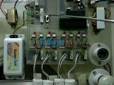 To correct power factor, first we need to find the current power factor. It can be find by taking tangent of ratio of time between zero crossing of current and voltageG‚waveformsG‚and two successive zero crossing of voltage waveform. Then it displays the calculated power factor in the 16G—2 LCD Display andG‚switchesG‚ON the capacitors if required. When load is connected the power factor is calculated by the PIC microcontroller. If the calculated power factor is less than 0. 9 then the relay switches on the capacitor. The relays are switched using ULN2003 which is basically a driver IC. ULN2003 consists of seven DARLINGTON PAIRS. The current lead in capacitor compensates the corresponding current lag which is usually present in loads. Hence the phase difference between the current and voltage will be reduced. Power Factor Correcting capacitor connected parallel to load through relay, if the relay is energized by microcontroller it will connect G‚the capacitor parallel with load, if relay deenergized it will remove the capacitor from the load. When the resistive load is on the power factor will be near to unity so the microcontrollerG‚doesn`tG‚energize the relay coil. When the inductive load is on the power factor decrease now the microcontroller energize the relay coil in order to compensate the excessive reactive power. Hence according to the load the power factor is corrected. //LCD Module Connections sbit LCD_RS at RB4_bit; sbit LCD_EN at RB5_bit; sbit LCD_D4 at RB0_bit; sbit LCD_D5 at RB1_bit; sbit LCD_D6 at RB2_bit; sbit LCD_D7 at RB3_bit; sbit LCD_RS_Direction at TRISB4_bit; sbit LCD_EN_Direction at TRISB5_bit; sbit LCD_D4_Direction at TRISB0_bit; sbit LCD_D5_Direction at TRISB1_bit; sbit LCD_D6_Direction at TRISB2_bit; sbit LCD_D7_Direction at TRISB3_bit; //End LCD Module Connections int powerFactor() { int a=0, b=0, t=0, x=0; float tm, pf; TMR1L=0; TMR1H=0; do { if(PORTA. F0 = 1) T1CON. F0 = 1; else if(PORTA. F0 = 0 && T1CON. F0 = 1) { T1CON. F0 = 0; break; } }while(1); a = (TMR1L | (TMR1H<<8) * 2; TMR1L=0; TMR1H=0; do { if(PORTA. F0 = 1) { T1CON. F0=1; if(PORTA. F1=1) { T1CON. F0=0; break; } } }while(1); b = TMR1L | (TMR1H<<8); tm = (float)b/a; pf = cos(tm*2*3. 14); x=abs(ceil(pf*100); return x; } void main() { char c[]=”0. 00″; int a, b, d, x, f, e; float tm, pf; Lcd_Init();
 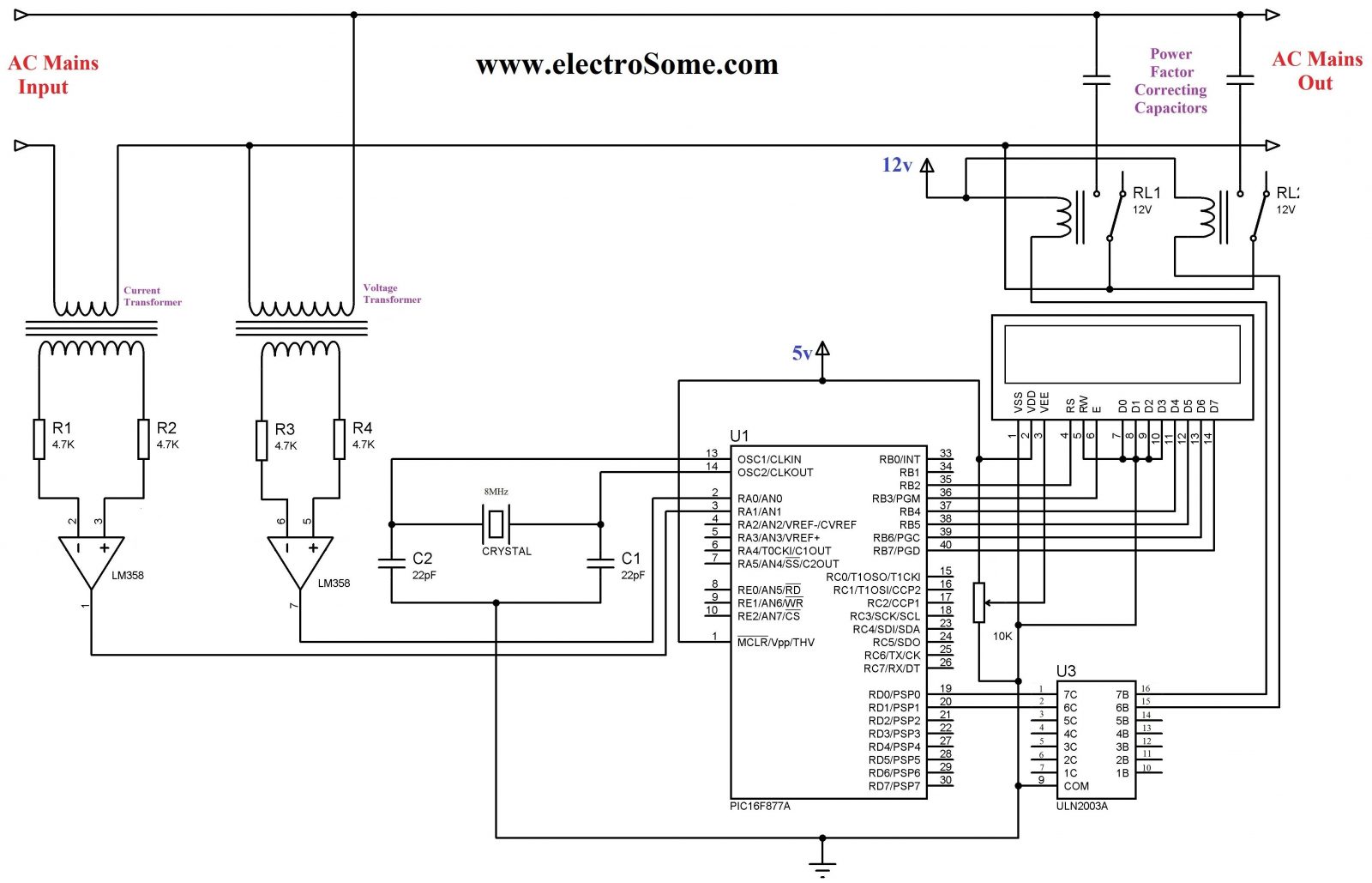 Lcd_Cmd(_LCD_CURSOR_OFF); // Cursor off ADCON1 = 0x08; // To configure PORTA pins as digital TRISA. F0 = 1; // Makes First pin of PORTA as input TRISA. F1 = 1; //Makes Second pin of PORTA as input TRISD. F0 = 0; //Makes Fist pin of PORTD as output TRISD. F1 = 0; //Makes Second pin of PORTD as output while(1) { a = powerFactor(); Delay_us(50); b = powerFactor(); Delay_us(50); d = powerFactor(); Delay_us(50); e = powerFactor(); Delay_us(50); f = powerFactor(); x = (a+b+d+f+e)/5; c[3]=x%10 + 0x30; x=x/10; c[2]=x%10 + 0x30; x=x/10; c[0]=x%10 + 0x30; Lcd_Out(1, 1, “Power Factor”); Lcd_Out(2, 1, c); if(x<90) { PORTD. F0 = 1; PORTD. F0 = 1; Delay_ms(2000); } else { PORTD. F0 = 0; PORTD. F0 = 0; } Delay_ms(250); } } The function powerFactor() will find the current power factor by using the Timer 1 module of PIC 16F877a. Power Factor may be fluctuating, so to avoid it we will find power facto
For more detail: automatic power factor controller using microcontroller
- How does the system extract current waveforms?
A current transformer is used to extract the waveforms of current. - What component acts as the heart of the controller?
The PIC 16F877A microcontroller is the heart of this Automatic Power Factor Controller. - How is the power factor calculated?
It is found by taking the tangent of the ratio of time between zero crossing of current and voltage waveforms and two successive zero crossing of voltage waveform. - When are the capacitors switched on?
If the calculated power factor is less than 0.9, the relay switches on the capacitor. - Which IC is used to switch the relays?
The relays are switched using ULN2003, which consists of seven Darlington pairs. - How does the capacitor correct the power factor?
The current lead in the capacitor compensates the corresponding current lag present in loads, reducing the phase difference. - What happens when a resistive load is connected?
When the resistive load is on, the power factor will be near to unity so the microcontroller doesn't energize the relay coil. - How does the system handle fluctuating power factors?
The function finds the power factor multiple times and averages the results to avoid fluctuations.