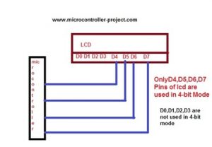
In this project i am going to interface 16×2 lcd display in 4-bit mode with Microchip Pic16f877 microcontroller. We can interface any size of character lcd display (8×1,8×2,10×1,10×2, 16×2,16×2,16×4,20×1,20×2,40×1,40×2 etc) in 4-bit mode with pic microcontrollers. In 4-bit interface mode only 4 lcd data lines are used to display data on lcd screen. Usually lcd is interfaced in 4-bit mode with microcontrollers to save I\O pins of microcontrollers. Before beginning any further i assume that you know difference between 4-bit and 8-bit lcd interfacing mode with microcntrollers. If not just take the below simple tutorial. Tutorial will help you in understating the basic difference, pros and cons of both the modes. It will also help you in understanding the code below easily.
16×2 lcd in 4-bit mode with pic microcontroller – Project requirements
- 16×2 character lcd.
- Pic 16f877.
- Potentiometer (For setting lcd contrast).
- Crystal(20MHz).
- Connecting wires.
- Bread board or PCB for the circuit.
- Power Supply.
16×2 lcd in 4-bit mode
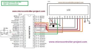
Interfacing 16×2 Lcd with pic microcontroller in 4-bit mode – Project circuit diagram
Taking the upper tutorial will led you know how 16×2 lcd works & how to configure it.The circuit diagram of the project is given below.
| #include <htc.h> | |
| #define _XTAL_FREQ 20e6 | |
| #define en RD7 | |
| #define rs RD6 | |
| #define rw RD5 | |
| void delay(unsigned int time) //Time delay function – Arbitrary delay | |
| { | |
| unsigned int i,j; | |
| for(i=0;i< time;i++) | |
| for(j=0;j< 5;j++); | |
| } | |
| //Function sending commands to the command register of LCD | |
| void llcdcmd(unsigned char value) | |
| { | |
| RB0=(value >> 0) & 0x01; | |
| RB1=(value >> 1) & 0x01; | |
| RB2=(value >> 2) & 0x01; | |
| RB3=(value >> 3) & 0x01; | |
| en = 1; //enable-e | |
| delay(500); | |
| en=0; //enable-e | |
| delay(500); | |
| } | |
| //Function sending data to the data register of LCD | |
| void ddisplay(unsigned char value) | |
| { | |
| RB0=(value >> 0) & 0x01; | |
| RB1=(value >> 1) & 0x01; | |
| RB2=(value >> 2) & 0x01; | |
| RB3=(value >> 3) & 0x01; | |
| en= 1; //enable-e | |
| delay(500); | |
| en=0; //enable-e | |
| delay(500); | |
| } | |
| void display(unsigned char c){ | |
| rs= 1; //register select-rs | |
| rw= 0; //read-write-rd | |
| delay(150); | |
| ddisplay(c>>4); //Send Higher nibble 4-bits of 8-bit data | |
| delay(150); | |
| ddisplay(c); //Send Lower nibble 4-bits of 8-bit data | |
| } | |
| void lcdcmd(unsigned char c){ | |
| rs= 0; //register select-rs | |
| rw = 0; //read-write-rd | |
| delay(150); | |
| llcdcmd(c>>4); //Send Higher nibble 4-bits of 8-bit command | |
| delay(150); | |
| llcdcmd(c); //Send Lower nibble 4-bits of 8-bit command | |
| } | |
| //Function to initialize the registers and pins of LCD | |
| //always use with every lcd of Hitachi | |
| void lcdint(void) | |
| { | |
| TRISB0=0; | |
| TRISB1=0; | |
| TRISB2=0; | |
| TRISB3=0; //Port-B is used as output port | |
| TRISD5=0; //Read-Write pin as output | |
| TRISD6=0; //Register select pin as output | |
| TRISD7=0; //Enable pin as output | |
| rw=0; | |
| rs=0; | |
| PORTB &= 0xF0; | |
| PORTB |= (0x03&0x0F); // Write 0x3 | |
| en = 1; | |
| delay(150); | |
| en = 0; | |
| delay(150); | |
| delay(4500); | |
| PORTB &= 0xF0; | |
| PORTB |= (0x03&0x0F); // Write 0x3 | |
| en = 1; | |
| delay(150); | |
| en = 0; | |
| delay(150); | |
| delay(300); | |
| PORTB &= 0xF0; | |
| PORTB |= (0x03&0x0F); // Write 0x3 | |
| en = 1; | |
| delay(150); | |
| en = 0; | |
| delay(150); | |
| delay(650); | |
| PORTB &= 0xF0; | |
| PORTB |= (0x02&0x0F); // Write 0x2 | |
| en = 1; | |
| delay(150); | |
| en = 0; | |
| delay(150); | |
| display(0x20); //Lcd in 4-bit mode, 1 line and 5×7 font character | |
| delay(1000); | |
| lcdcmd(0x28); //Lcd in 4-bit mode, 2 Line and 5×7 font character | |
| delay(50); | |
| lcdcmd(0x0C); //Display on cursor off | |
| delay(50); | |
| lcdcmd(0x01); //Clear Lcd Screen | |
| delay(50); | |
| lcdcmd(0x06); //Entry Mode | |
| delay(50); | |
| lcdcmd(0x80); //Start from first line | |
| delay(50); | |
| } | |
| void main() | |
| { | |
| lcdint(); //Initialize character lcd | |
| display(‘M‘); display(‘i‘); display(‘c‘); display(‘r‘); display(‘o‘); display(‘c‘); | |
| display(‘o‘); display(‘n‘); display(‘t‘); display(‘r‘); display(‘o‘); display(‘l‘); | |
| display(‘l‘); display(‘e‘); display(‘r‘); | |
| lcdcmd(0xC0); //Jump to second line | |
| display(‘M‘); display(‘i‘); display(‘c‘); display(‘r‘); display(‘o‘); display(‘c‘); | |
| display(‘o‘); display(‘n‘); display(‘t‘); display(‘r‘); display(‘o‘); display(‘l‘); | |
| display(‘l‘); display(‘e‘); display(‘r‘); | |
| lcdcmd(0x01); //Clear lcd | |
| delay(500); | |
| } |
About The Author
Muhammad Bilal
I am a highly skilled and motivated individual with a Master's degree in Computer Science. I have extensive experience in technical writing and a deep understanding of SEO practices.