Summary of Wisp628 an in-circuit flash PICmicro Programmer
The Wisp628 is an in-circuit programmer for flash PICmicro chips, enabling rapid code/program/test cycles without removing the chip. It draws 5V power from the target circuit and uses a serial interface with passthrough capabilities. The device supports High Voltage Programming (HVP) via a charge pump to generate 13V on the /MCLR pin. While primarily a prototype programmer, it can support production-grade tasks if the target's Vcc is varied. It replaces the older 16F628-based design with a newer 16F628 microcontroller and includes provisions for chips where /MCLR is configurable as an input.
Foremost Wisp628 is an in-circuit programmer. The programmer is connected to a few pins of the target PICmicro, which is programmed while it remains in the circuit. The target circuit must be compatible with the programmer to make this in-circuit programming possible.
Wisp628 is designed to be used as an in-circuit programmer only, hence no socket is provided for the target chip. ‘Why use such a limited design’, you might ask, ‘an ex-circuit programmer with a ZIF socket can do the same things and more!’ You are partially right, but consider the way you would use and ex-circuit programmer for development: take the chip from its circuit, put it in the programmer, program it, take it from the programmer, put it in its circuit, test. Of course, you can do that, no problem. But think of how many times you will have to do that before your program is working satisfactory, and how many chip pins you will break in the process. Now compare that to in-circuit programming: you will have to spend some time to prepare the circuit for in-circuit programming, and to make the right connections (but this can be as easy as clipping a DIL clip onto the target chip!). But after this has been done you can sit behind your PC and code, compiler, program (download) and debug, without touching the target circuit. Believe me, after working this way once you will regret going back!
Wisp628 is a High Voltage Programming (HVP) programmer: it applies 13 Volt to the /MCLR pin of the target PICmirco to put it in programming mode. Wisp628 uses a charge pump to create this voltage, so it can not provide much current. This is OK for flash PICmicro’s (which use the voltage only to enable programming), but not for EPROM chips (which use the 13 Volt to power the actual programming, requiring substantial current).
The following target chips are currently supported :
chips that are shown in square brackets are supported conform Microchip’s programming specifications, but have have not been tested with a real chip
although not explicitly mentioned the LF (low power) variants of the mentioned chips are also supported
programming chips that can configure their /MCLR pin as input can (especially when this feature is used) requires an additional circuit
A special note for the 18FXX39 chips: these chips have the same on-chip identification code as the (very similar) 18FXX2 chips. when you want to read the image of an 18FXX39 be sure to specify the target chip explicitly to the programmer softeware, otherwise the full 18FXX2 address range will be read, instead of the slightly smaller 18FXX39 address range, which would cause a verification error when you later try to write such an image to an 18FXX39 chip.
Wisp628 supports a rapid development cycle: without even touching the target hardware you can program the target, reset the chip, start the programmed application, and even communicate with it.
Microchip (the manufacturer of the PICmicro chips) makes a distinction between production programmers, which verify the programming at the extremes of the Vcc levels that are to be expected in the target circuit, and prototype programmers, which verify at one Vcc level only. Wisp628 derives its power from the target circuit, hence it is a prototype programmer. Note that you can use Wisp628 for occasional production-grade programming, but then you must vary the Vcc of the whole circuit (including Wisp628), for instance by using a variable power supply.
Wisp628 takes its power from the target circuit, which must provide a stable 5V @ 20mA (4.5 .. 5.5 Volt will work). The PICmicro in the Wisp628 can run on a lower voltage, but then the charge pump might not be able to generate a voltage that is high enough to put the target in programming mode.
Wisp628 uses a serial interface with a simple yet robust protocol. Neither the timing of the communication nor the RS-232 levels produced by the PC will affect the programming. Wisp628 iteself produces a true RS-232 level signal.
The PC-to-programmer connection requires a 9-pin serial extension cable (male at one side, female at the other side, straight connections, hence not a null-modem cable).
Wisp628 provides a serial passthrough which is usefull when you want to communicate with your target system. The same serial line that is connected to the Wisp628 programmer can be passed on to the target PICmicro’s pins RB6 + RB7 (the ones that are already used for programming), or – using additional wires from Wisp628 to the target PICmicro – any pair of pins (most likely: the pins that are connected to the targets build-in UART). The passthrough is implemented in software, so it is best used with baudrates of 19k2 and lower. The passthrough can handle both inverted and non-inverted signal levels at the target PICmicro side.
Wisp628 is derived from the older WISP (16×84 based) design, but replaces the obsolete 16×84 with the newer (and cheaper) 16F628.
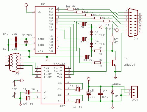
Circuit
ed.
While programminging the charge pump is active. It produces a Vpp (programming enable voltage) of 3 times Vcc (5 Volt) minus 3 diode drops. Transistor T1 is used to switch the Vpp. Capacitor C8 bridges short periods in which the PICmicro does not cycle the charge pump. Note that the source of the charge pump is not Vcc but a pin of IC2 (which is at or near Vcc level). This was done to make it easier for me to design a PCB. Feel free to connect D2 to Vcc instead.
T1 is specified as a 2n3904, which a very cheap American transistor, but sometimes not readily available in other countries. Feel free to substitute another small-signal transistor (in an early version I used a bc547).
The PICmicro uses a standard 20MHz Xtal with accompanying capacitors. The 16F628 is configured for internal reset, so /MCLR is not connected.
The target connector is a D15M connector. Only the ‘top’ row of 8 pins is used. This makes it possible to use a solder cup connector fitted in ‘card edge’ style. All lines to the target (except Gnd and Vcc) have 470 ohm series resistor to damp line reflections and to offer some protection against wrong connections (the circuit diagram shows 47 ohm, which is OK too).
The target connector provides
Gnd and Vcc (remember that Wisp628 takes its power from the target circuit)
the three programming lines (to be connected to RB6, RB7 and /MCLR of the target)
an optional fourth programming line that pulls the LVP enable pin of the target PICmicro down
two more optional ‘programming’ lines that can be used to communicate with the target
When you make a PCB or otherwise build your Wisp628 remember that
C11 should be as close to the Gnd and Vcc pins of the 16F628 as possible
the leads from the 16F628 to C9, C10 and Q1 should be short
the earthed side of C9 and C10 should connect directly to the Gnd pin of the 16F628
Additional circuit
The Wisp628 circuit as described above is designed to apply Vpp (the programming enable voltage) to the /MCLR pin while Vcc (power) to the target PIC is active. Some newer PICs can configure their /MCLR pin as input. These chips will (in most cases) fail to get into programming mode with the standard Wisp628 circuit when the /MCLR pin is indeed configured as input. The circuit below can be inserted between the Wisp628 and the target PIC to solve this problem. Its main function is to short the target PICs power very briefly (a few milliseconds). The diode ensures that the Wisp628 still has power during this brief period. In some cases it might be necesarry to add a bigger elco on the Wisp628 Gnd and Vcc pins (1000 uF or more), or use separate +5 Volt power supplies for the target and for the Wisp628 programmer. In any case the power to the target PIC must tolerate the brief short, it must not deliver more current than the TIP120 can handle (a few Ampere), and it must recover fast. A 7805 or 78L05 based power supply will do fine, some lab power supplies will not, because they are designed to ‘fold back’ after an overcurrent situation and recover slowly. In such cases a 10 Ohm resistor in series with the ppwer supply might solve the problem.
Note that the additional circuit might make the programming of some older PICs impossible, and using the serial passthrough with the ‘extra’ pins will inadvertently enable the circuit, so it might be a good idea to make the circuit removeable. The picture below shows a ‘dongle’ style implementation that can be fitted (or not) as needed.
How does the Wisp628 power itself? The programmer takes its power directly from the target circuit, requiring a stable 5V at 20mA.
Can I use the Wisp628 with EPROM chips? No, the Wisp628 cannot provide enough current for EPROM chips because it uses a charge pump that only supplies voltage, not substantial current.
What type of cable connects the PC to the programmer? A 9-pin serial extension cable with straight connections (male to female) is required; a null-modem cable should not be used.
Does the Wisp628 support chips where the MCLR pin is configured as an input? The standard circuit may fail for these chips; an additional circuit involving a brief power short or a dongle is needed to solve this problem.
What is the maximum recommended baud rate for serial passthrough? The passthrough is best used with baud rates of 19k2 and lower due to its software implementation.
How does the Wisp628 achieve programming mode for the target chip? It applies 13 Volts to the /MCLR pin using a charge pump to put the target into programming mode.
Is the Wisp628 suitable for production environments? It is designed as a prototype programmer verifying at one Vcc level, but can be used for occasional production work if the whole circuit's Vcc is varied.
Which pins are used for the serial passthrough feature? The same serial line connected to the programmer can be passed to the target's RB6 and RB7 pins or any other pair of pins via additional wires.
I am an experienced technical writer holding a Master's degree in computer science from BZU Multan, Pakistan University. With a background spanning various industries, particularly in home automation and engineering, I have honed my skills in crafting clear and concise content. Proficient in leveraging infographics and diagrams, I strive to simplify complex concepts for readers. My strength lies in thorough research and presenting information in a structured and logical format.
This website uses cookies to improve your experience. We'll assume you're ok with this, but you can opt-out if you wish. ACCEPTCheck Privacy Policy
Manage consent
Privacy Overview
This website uses cookies to improve your experience while you navigate through the website. Out of these, the cookies that are categorized as necessary are stored on your browser as they are essential for the working of basic functionalities of the website. We also use third-party cookies that help us analyze and understand how you use this website. These cookies will be stored in your browser only with your consent. You also have the option to opt-out of these cookies. But opting out of some of these cookies may affect your browsing experience.
Necessary cookies are absolutely essential for the website to function properly. This category only includes cookies that ensures basic functionalities and security features of the website. These cookies do not store any personal information.
Any cookies that may not be particularly necessary for the website to function and is used specifically to collect user personal data via analytics, ads, other embedded contents are termed as non-necessary cookies. It is mandatory to procure user consent prior to running these cookies on your website.