For my current project I searched for a good boost power converter which is able to deliver continuous 400mA power for various sensors.
There are an endless number of good boost converters around, but not many can be hand soldered to a board. I would really like to see some like the TPS61092 with SOIC or similar packages. The biggest problem seems to be the heat transport, why most chips have to be mounted flat on the board.
Before using the chip in my project, I created a small test board. Using this board I can test various things. First I liked to test the performance under load. Next I tested if the chip can be hand soldered and finally I tested the final board layout I will use in my project.
PERFORMANCE
The performance of this chip is really good, producing a very stable output. I designed everything for a load up to 2A with all suggested components from the specification. There will never be a higher load than 0.5A, so I probably could use a smaller coil for the final project.
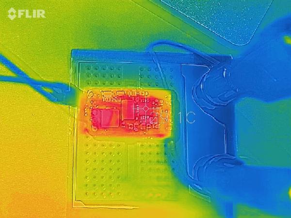
Running under 0.5A load from 3.3V for over half an hour, the chip stays quite cold. Even in my case, where the chip bottom is not directly soldered to the board, it seems to be able to transfer the heat into the board. This is nicely visible in the thermal image of the board.
The schema lacks the correct labels for the connectors, see the silkscreen on the bottom of the board to see the meanings of the connectors.
The board looks great, especially the silk screen is incredible precise. All these labels are only 1mm in height. There is just a small misalignment between the copper layer and the solder mask (<0.05mm).
Read More: TESTING THE TPS61092 BOOST CONVERTER

