Summary of Temperature controlled fan using PIC 16F877A
This embedded system automatically controls a DC motor's speed based on external temperature readings. Using an LM35 sensor to detect temperature changes, the microcontroller processes the analog data via its A/D channel. The system adjusts the motor speed through Pulse Width Modulation (PWM), increasing speed as temperature rises and decreasing it as temperature falls, effectively acting as an automated cooling fan.
Parts used in the Temperature Controlled Fan System:
- LM35 Temperature Sensor
- Microcontroller with A/D channel
- PWM module
- DC Motor
- L293D Driver IC
You might have come across several applications where we need to control a specific device based on analog parameter. This Embedded system works in a similar concept where we are about to control the speed of a DC motor using based on the external temperature. The rise in temperature will result in increase in speed of the motor and vice versa. These type of Temperature controlled fan systems can generally be used to maintain temperature of a room or object automatically.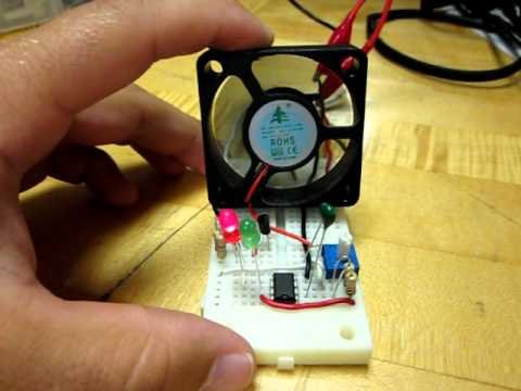
DESIGN OF TEMPERATURE CONTROLLED FAN SYSTEM:
- The temperature is measured by means of a temperature sensor LM35.
- The output voltage of the sensor is fed to the A/D channel of the Microcontroller.
- Based on the sensed temperature the speed of the motor is controlled using PWM .
- Several temperature ranges was set in the code to vary the motor speed based on the level of temperature sensed.
- The speed of the motor is controlled by using PWM.
- The motor is driven using a driver IC l293D, See a brief explanation on its working and wiring here.
LM35:
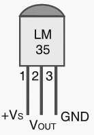
Lm 35 is used to sense the external temperature which is capable of sensing temperature ranges from -55 to 150 C. The output voltage is proportional to the temperature hence there is no need of trimmers to calibrate the reading. The output voltage of this sensor varies by 10mv per degree change in temperature.
CALIBRATION:
We are using a 10 bit ADC and Vcc as Vref to the ADC module of the Controller. So in order to determine the step size we have to divide the Vref by our resolution that is 2^10 ( 1024 ).
Step Size = 5 / 1024 = 4.83mV
We obtain a change of 10mV with each rise or fall in temperature from the sensor. And value in the ADC register will alter by two steps with each degree change in the sensor since two increments of step size i.e 4.833mV * 2 = 9.96mV which is approximately equal to 10mV. So in order to obtain the original value we have to divide the contents in the ADC register by 2
For more detail: Temperature controlled fan using PIC 16F877A
- How does the system control motor speed?
The speed is controlled using PWM based on the sensed temperature level. - What component measures the external temperature?
An LM35 temperature sensor is used to measure the temperature. - Can the LM35 sensor sense temperatures below zero?
Yes, the sensor can sense temperature ranges from -55 to 150 C. - Does the LM35 require calibration trimmers?
No, there is no need for trimmers because the output voltage is proportional to the temperature. - How much does the output voltage change per degree?
The output voltage varies by 10mv per degree change in temperature. - What resolution does the ADC use in this design?
A 10 bit ADC is used with Vcc as the reference voltage. - How do you calculate the original temperature value from the ADC register?
You must divide the contents in the ADC register by 2 to obtain the original value. - Which driver IC is used to drive the motor?
The motor is driven using a driver IC l293D.