First of all, the circuit is quite complicated can a design professional experienced individuals work:), I think, but some of the sections, and the Sine Wave inverter circuit diagram source code written in C language can be useful for… Electronics Projects, Sine Wave Inverter Circuit with PIC16F876 Microcontroller “microchip projects, microcontroller projects, pic16f876 projects,
First of all, the circuit is quite complicated can a design professional experienced individuals work:), I think, but some of the sections, and the Sine Wave inverter circuit diagram source code written in C language can be useful for different projects themselves.
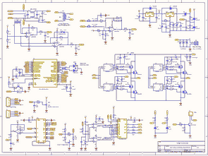
Sine Wave inverter circuit built on all the floors Pic16f876 separately circuit diagram is specified the current sensing, voltage detection, feeding, etc.
Circuit diagram, spares list c and Schematic Capture file (hex codes and Altium Designer.SchDoc):
FILE DOWNLOAD LINK LIST (in TXT format): LINKS-10292.zip
Source: SINE WAVE INVERTER CIRCUIT WITH PIC16F876 MICROCONTROLLER
About The Author
Muhammad Bilal
I am a highly skilled and motivated individual with a Master's degree in Computer Science. I have extensive experience in technical writing and a deep understanding of SEO practices.