Summary of Real time clock with remote control and ST7735 TFT display
This article details building a remote-controlled real-time clock using a PIC18F4550 microcontroller, DS1307 RTC chip, and an ST7735R TFT display. The system utilizes an RC-5 IR remote to set the time and date, with decoding handled via a specific state machine. The design integrates an 8MHz oscillator for the microcontroller and a 32.768KHz crystal for the RTC, powered by a +5V source and a backup battery.
Parts used in Real Time Clock with Remote Control:
- PIC18F4550 Microcontroller
- ST7735R (ST7735S) 1.8" SPI TFT Display
- DS1307 RTC Chip
- RC-5 IR Remote Control
- IR Receiver
- 8MHz Crystal Oscillator
- 32.768KHz Crystal Oscillator
- 2 x 22pF Ceramic Capacitors
- 47uF Capacitor
- 3 x 10K Resistor
- 5 x 1K Resistors
- 3V Lithium Coin Cell Battery
- +5V Power Supply Source
- Breadboard
- Jumper Wires
(Some knowledge about RC-5 protocol is required)
This project shows how to build a remote controlled real time clock with TFT display using PIC18F4550 microcontroller.
In this project DS1307 RTC is used as a real time clock chip and the remote control is an IR (infrared) remote control which uses RC-5 communication protocol, this remote control is used to set time and date. The device used t display time and calendar is 1.8″ ST7735R (ST7735S) SPI TFT display.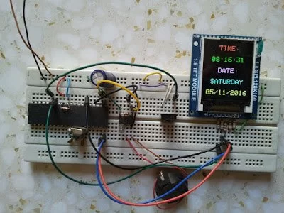
To display the ST7735 TFT display with PIC18F4550 microcontroller we need a driver, this driver and some other details about this display can be fount at the following url:
ST7735 SPI TFT Display Driver for CCS PIC C compiler
And the post at the following link shows how to interface this display with PIC18F4550 microcontroller:
Interfacing PIC18F4550 with 1.8″ TFT display
Or simply you can download the ST7735 TFT driver from the following link:
ST7735 SPI TFT Display Driver
The method used to decode RC-5 signals is described in the following topic:
RC5 IR Remote Control Decoder with PIC12F1822 Microcontroller
The decoding process follows the state machine show below: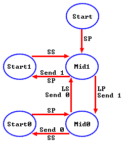
Where:
SP : Short Pulse (About 889µs)
LP : Long Pulse (About 1778µs)
SS: Short Space (About 889µs)
LS : Long Space (About 1778µs)
Basically there are 4 states: Mid1, Mid0, Start1 and Start0.
Components List:
- PIC18F4550 Microcontroller
- ST7735R (ST7735S) 1.8″ SPI TFT Display
- DS1307 RTC Chip
- RC-5 IR Remote Control
- IR Receiver
- 8MHz Crystal Oscillator
- 32.768KHz Crystal Oscillator
- 2 x 22pF Ceramic Capacitors
- 47uF Capacitor
- 3 x 10K Resistor
- 5 x 1K Resistors
- 3V Lithium Coin Cell Battery
- +5V Power Supply Source
- Breadboard
- Jumper Wires
For the DS1307 RTC chip there are many topics in this blog talking about it and how to interface it with different types of PIC microcontrollers for example the topic at the url below:
Real time clock with PIC18F4550 and DS1307 RTC
Real time clock with remote control and ST7735 TFT display circuit:
The following image shows our project circuit schematic where the microcontroller runs with 8MHz external crystal oscillator.
For more Detail: Real time clock with remote control and ST7735 TFT display
- How is the time set on this device?
The time and date are set using an IR remote control that uses the RC-5 communication protocol. - What driver is needed for the ST7735 display?
A driver for the CCS PIC C compiler is required to interface the ST7735 TFT display with the PIC18F4550. - Which microcontroller powers the project?
The PIC18F4550 microcontroller runs the entire device including the display and RTC logic. - What crystals are used in the circuit?
An 8MHz crystal oscillator is used for the microcontroller and a 32.768KHz crystal is used for the DS1307 RTC. - How does the RC-5 signal decoding work?
The process follows a state machine with four states: Mid1, Mid0, Start1, and Start0 based on pulse and space durations. - What components define the pulse lengths in RC-5?
Short Pulse is about 889µs, Long Pulse is about 1778µs, Short Space is about 889µs, and Long Space is about 1778µs. - How is the DS1307 chip powered during outages?
A 3V Lithium Coin Cell Battery provides power to maintain the real-time clock data. - Can I find code examples for this project online?
Yes, drivers and interfacing tutorials are available at the provided links for ST7735 and RC-5 decoders.