
Summary of projects or dual channel inductive loop vehicle detector
This article details a dual-channel inductive loop vehicle detector featuring four operating modes, automatic tuning, and adjustable sensitivity. The hardware utilizes a single oscillator with multiplexed loops to detect frequency changes for vehicle presence, direction, and speed trapping. It includes robust protection against lightning and operates across a wide temperature range.
Parts used in the Dual Channel Inductive Loop Vehicle Detector:
- Dual Channel Loop Detector PCB (v1.2 or v1.3)
- Single Oscillator
- Multiplexer Circuit
- PNP Transistors (connected in parallel opposite directions)
- RA4/T0CKI Pin Interface
- Galvanic Isolation Component
- Gas Discharge Tube
- PC Configurator Software Source Code
- User Manuals (PDF format)
Specifications
- Number of operating modes: 4
- Tuning: Automatic
- Detection type: Presence/Pulse
- Presence time: Adjustable in 3 steps
- Pulse duration: 250 ms / 500 ms
- Signal filtering: Adjustable in 2 steps (NORMAL, HIGH)
- Loop inductance: 20 uH – 1000 uH
- Frequency range: 20 kHz – 145 kHz
- Frequency selection: 2 combinations (LOW, HIGH)
- Sensitivity: Maximum 0.0025\% Δf/f, adjustable in 8 steps
- Detection speed: 10 ms by default, adjustable
- Start-up time: ~ 1 second per channel (or longer if frequency is not stable)
- Power supply: 12-40 V DC / 9-28 V AC (only for standalone version)
- Current consumption: ~ 0.035 A
- Temperature range: -35°C – 120°C
- Sensor protection: Galvanic isolation + gas discharge tube for lightning protection
- Dimensions: 8,5cm x 7cm
User Manuals and PC Configurator software source code
All user manuals are available for download in the ZIP archive (the red download button under the article). However, here is also a direct link for the user manual for PCB v1.2, FW v1 on this link (PDF), and for PCB v1.3, FW v1 here (PDF).
PC Configurator user manual is here (PDF) and source code is on GitHub here.
Modes of operation
- Single Channel (only A)
- Dual Channel Independent A & B
- Dual Channel Directional Logic A + B
- Speed Trap A + B
Hardware
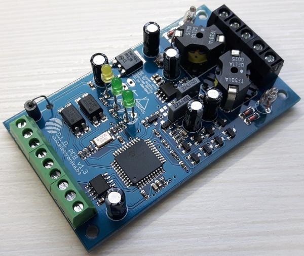
Hardware differs from previous version in many ways but the essence is the same – it counts pulses coming into RA4/T0CKI pin and performs the same filtering and calculations in order to detect the change in frequency of oscillation. This time, it does that twice for both channels independently.
There were two possibilities on how to implement dual channel loop detector and one of them (and unfortunately widely used) is by using two independent oscillators on board while having them enabled/disabled one at a time in order to read loop A and loop B frequency. The other method is by multiplexing two (or more) loops on one single oscillator on board. I have chosen the second method because it just seams better to have one oscillator and two loops instead of two oscillators each connected to one loop.
It was quite tricky to enable/disable a loop in an oscillator so in the end I had to offset the multiplexer circuit to half of supply voltage (Vcc/2) and opted to use simple PNP transistors connected in parallel but in opposite direction so that one conducts positive half-wave and the other one negative half-wave of the oscillator signal. I first tried using CD4066 but with no luck.
Read More: projects/dual channel inductive loop vehicle detector
-
How many operating modes does the detector support?
The device supports four operating modes including Single Channel, Dual Channel Independent, Dual Channel Directional Logic, and Speed Trap. -
What method was chosen for implementing the dual channel loop detection?
The author chose multiplexing two loops on one single oscillator instead of using two independent oscillators. -
Why were CD4066 chips not used in the design?
The designer first tried using CD4066 but had no luck enabling and disabling the loop in the oscillator. -
How are the PNP transistors connected in the circuit?
Simple PNP transistors are connected in parallel but in opposite directions so that one conducts the positive half-wave and the other the negative half-wave. -
What is the power supply requirement for the standalone version?
The standalone version requires a power supply of 12-40 V DC or 9-28 V AC. -
Does the detector offer adjustable sensitivity settings?
Yes, sensitivity is adjustable in 8 steps with a maximum of 0.0025% Δf/f. -
What components provide sensor protection against lightning?
Sensor protection is provided by galvanic isolation and a gas discharge tube. -
Can the presence time be adjusted?
Yes, the presence time is adjustable in 3 steps.

