
Summary of PIC16F84 DEVELOPMENT BOARD PLAY-PIC
This article introduces the PLAY-PIC, a PIC16F84 development board ideal for beginners. It features integrated buttons, LEDs, and seven-segment displays, along with connectors for external LCDs and programmers. The board includes a 9-24V DC voltage regulator circuit to power the system easily.
Parts used in the PIC16F84 Development Board PLAY-PIC:
- PIC16F84 microcontroller
- Buttons
- LEDs
- Seven-segment displays
- LCD display connector
- External programmer connector
- Internal card connectors
- 9-24 volts DC voltage regulator circuit
New to PIC programming a circuit that will be beneficial to your friends. Designed to work with PIC16F84. On the board buttons, LEDs and available in seven segments. Thus, when a trial programs çalıştırabilirsiniz.ayrı…Electronics Projects, PIC16F84 Development Board PLAY-PIC “pic development board, pic16f84 projects, “
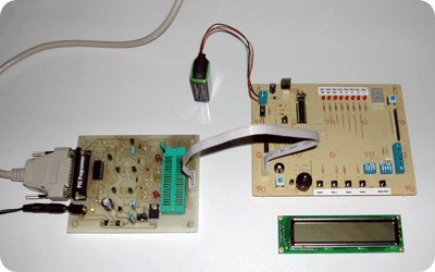
New to PIC programming a circuit that will be beneficial to your friends. Designed to work with PIC16F84. On the board buttons, LEDs and available in seven segments. Thus, when a trial programs çalıştırabilirsiniz.ayrı easily make links to outside input, LCD display and an external programmer for connection of the card’s internal connectors bulunmakta.ayrı var.9-24 volts DC voltage regulator circuit can be fed with a source.
PIC16F84 PLAY-PIC

PIC16F84 Development Board PLAY-PIC pcb schematic: PIC16F84 Development Board PLAY-PIC.RARauthor>CoşkunTAŞDEMİR
-
What is the primary purpose of the PLAY-PIC board?
It is designed for beginners new to PIC programming to create circuits beneficial to friends. -
Which microcontroller does this board support?
The board is specifically designed to work with the PIC16F84. -
What components are available directly on the board?
The board includes buttons, LEDs, and seven-segment displays. -
Can I connect external devices to this board?
Yes, you can easily make links to outside inputs, LCD displays, and an external programmer via internal connectors. -
What voltage range powers the board?
A 9-24 volts DC voltage regulator circuit allows the board to be fed with a source within that range. -
Who authored the PCB schematic for this project?
The author of the schematic is Coşkun TAŞDEMİR. -
How can users test their programs on this board?
Users can run trial programs directly on the board once connected.
