Summary of PIC12F675 internal EEPROM code and Proteus simulation
This article details C language code for reading and writing data to the internal EEPROM of a PIC12F675 microcontroller using MPLAB and HI-TECH C. The 128-byte memory space is addressed from 0x00 to 0x7F. A Proteus simulation demonstrates functionality, where an LED on GP0 illuminates to confirm successful EEPROM programming.
Parts used in the PIC12F675 Internal EEPROM Project:
- PIC12F675 microcontroller
- LED
- MPLAB v8.85 IDE
- HI-TECH C v9.83 compiler
- Proteus v7.10 simulator
This post provides the internal EEPROM reading and writing code for PIC12F675 microcontroller.
As we know, PIC12F675 microcontroller has 128 bytes of built in EEPROM data space with an address range of 0x00 to 0x7F. This code is written in C language using MPLAB with HI-TECH C compiler. You can download this code from the ‘Downloads‘ section at the bottom of this page.
It is assumed that you know how to blink an LED with PIC12F675 microcontroller. If you don’t then please read this page first, before proceeding with this article.
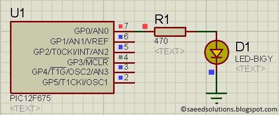
The result of simulating the code in Proteus is shown below.
In the above circuit[1], LED attached on GP0 indicates weather a byte was successfully written in the internal EEPROM or not. In the above figure, LED is ON which indicates that EEPROM was successfully programmed.
Code
The code for the main function is shown below.
Downloads
EEPROM code for PIC12F675 was compiled in MPLAB v8.85 with HI-TECH C v9.83 compiler and simulation was made in Proteus v7.10. To download code and Proteus simulation click here.
For more detail: PIC12F675 internal EEPROM code and Proteus simulation
- What is the address range of the built-in EEPROM data space?
The address range is 0x00 to 0x7F. - How many bytes of internal EEPROM does the PIC12F675 have?
The microcontroller has 128 bytes of built-in EEPROM data space. - Which compiler was used to write the code?
The code was written using the HI-TECH C compiler. - What software was used for the simulation?
The code was simulated in Proteus v7.10. - Which pin indicates if a byte was successfully written?
An LED attached on GP0 indicates the status. - What does it mean when the LED is ON in the circuit?
It indicates that the EEPROM was successfully programmed. - Can I download the code and simulation files?
Yes, you can download them from the Downloads section at the bottom of the page. - Is knowledge of blinking an LED required before starting?
Yes, it is assumed that you know how to blink an LED with this microcontroller.