Summary of Naked Clock using PIC16F877 Microcontroller
Summary: A bare-bones PIC clock was built without a nonfunctional enclosure; the hanger doubles as ground. It uses a PIC16F877 microcontroller, was calibrated by running and adjusting code for timing, and was moved from battery to wall power after 9V battery life proved insufficient. Shared resistors cause variable LED segment brightness, especially on the seven segment, suggesting per-segment resistors would be better.
Parts used in the Naked Clock:
- PIC16F877 microcontroller (40-pin)
- Seven-segment LED displays
- Resistors (shared between multiple LED segments)
- Hanger used as ground connection
- Wall adapter (DC power supply)
- Wiring/PCB or breadboard connections
- Supporting passive components used with the PIC (capacitors, crystal or oscillator components as implied)
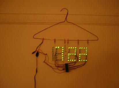
Why have an enclosure? The enclosure of a clock doesn’t tell you the time! So I built this PIC clock with no part that doesn’t serve an electrical function. The hanger is the ground.
Lessons Learned:
I originally planned to have this run off a 9 volt battery, but I found that it would drain the battery in less than 24 hours, not an ideal clock! So now it runs off a wall adapter.
There’s a resistor between the LEDs and the ground that is the hanger. Since several segments share one resistor, the brightness of one segment depends on how many of its neighbors are on. The seven digit has the biggest problem.
It would have been better to put the resistor between each pin and LED segment instead.
For more detail: Naked Clock using PIC16F877 Microcontroller
- Why have an enclosure?
The builder chose no enclosure because the clock enclosure does not tell time, so every part was made to serve an electrical function and the hanger is the ground. - What microcontroller is used?
The PIC16F877 40-pin microcontroller is used. - How was the clock timing calibrated?
The builder let the clock run for a few weeks to observe drift, then adjusted the code by adding an extra delay to get timing right. - Why was battery power abandoned?
A 9 volt battery drained in less than 24 hours, so the clock now runs off a wall adapter. - How is ground implemented?
The hanger serves as the ground connection. - Why do LED segment brightnesses vary?
Several segments share one resistor, so a segment's brightness depends on how many neighboring segments are on. - Which digit has the worst brightness problem?
The seven digit has the biggest problem with brightness variation. - What improvement was suggested for LED resistors?
Placing a resistor between each pin and each LED segment would have been better.