Summary of My New MIDI Merger uses 10 MIPS £1.00 PIC Microcontroller using PIC18F4320
This article details a DIY MIDI Merger unit featuring four autonomous inputs and one output, utilizing a PIC18F4320 microcontroller. The project includes an LED channel indicator, supports software expansion via a bootloader, and offers features like volume control, channel reassignment, and command filtering. The design separates the main logic from a user interface board with a key matrix and LEDs.
Parts used in the MIDI Merger:
- PIC18F4320 microcontroller
- Crystal oscillator
- Four 6N138 opto-isolators
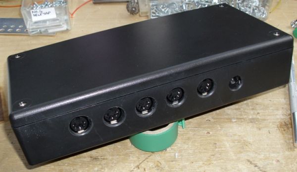
- Five on-board DIN sockets
- Voltage regulator
- Resistors (10K value)
- Capacitor (100nF)
- Small TACT switches
- Extra-bright 3mm LEDs
- Two double-row pin headers
- 16-key matrix keypad
This unit provides 4 autonomous MIDI inputs and 1 MIDI output. Note this is a ‘proper’ MIDI Merger – all 4 MIDI inputs can be used at the same time, unlike other ‘designs’. The unit also provides an indication of the channel number being played, and has shown itself to be capable of expansion into a full-blown controller.
The PIC microcontroller I used – 18F4320 was being sold off cheap, at £1.00 each by Crownhill Associates, in Ely – but don’t pester them for any 18F4320’s at this give-away price, as I bought the rest of their stock!
It’s always worthwhile to take a glance at their website, as inevitably they have PICs at discounts you wouldn’t find anywhere else. A purchase I made this week, was 5 PIC18F6620s – a 64-pin TQFP monster PIC – at only £2.00 per pop!
The intention here is to provide details of the schematic and photographs/advice on construction. The PIC code will be discussed more fully on http://picprojects.info.(shortly) All source-code is provided in this post, together with Eagle project files for the printed circuit boards.
The schematic is below. Apart from the PIC and it’s crystal, the other main components are 4 6N138 opto-isolators, 5 on-board DIN sockets, a voltage regulator, and a few resistors. I mounted the LEDs on a separate interface/indicator board, and the schematic for this is shown later. The handful of pin headers are used to add a key matrix and FTDI USB-TTL lead, for upgrading the software, using an internal bootloader.
Following are some views of the PCB. Note these are not all to the same scale. The complete Eagle project for the PCB is available for download.
As shown in the main schematic, the unit functions as a MIDI-Merger and Indicator. With the addition of a keypad, extensions to this are easily added. I added the following, mainly because I find them useful.
- MIDI Minimum volume (set on a channel-by-channel basis)
- MIDI Channel re-assign – Re-assign any MIDI Channel to another
- Filter-out unwanted MIDI commands – Get rid of those pesky pitch-wheel messages from your MIDI Guitar Unit!
The front panel I have shown above – I created a separate user-interface board that incorporated a 16-key matrix, and duplicated the reset switch and LEDs.
The 4 resistors are 10K in value and the capacitor is 100nF. I used small TACT switches and extra-bright 3mm LED’s. I used 2- double-row pin headers to connect everything to the main board.
For more detail: My New MIDI Merger uses 10 MIPS £1.00 PIC Microcontroller using PIC18F4320
- How many autonomous MIDI inputs does this unit provide?
The unit provides 4 autonomous MIDI inputs. - What is the specific microcontroller model used in this project?
The author used a PIC18F4320 microcontroller. - Can all four MIDI inputs be used simultaneously?
Yes, this is a proper MIDI Merger where all 4 inputs can be used at the same time. - What components are used for isolating the MIDI signals?
The schematic uses four 6N138 opto-isolators. - Does the unit indicate which channel is currently playing?
Yes, the unit provides an indication of the channel number being played. - What additional features can be added by expanding the unit?
Extensions include setting minimum volume per channel, re-assigning MIDI channels, and filtering unwanted commands. - How is the software upgraded on this device?
Software is upgraded using an internal bootloader and an FTDI USB-TTL lead connected via pin headers. - What type of switches were used for the user interface?
Small TACT switches were used for the interface.