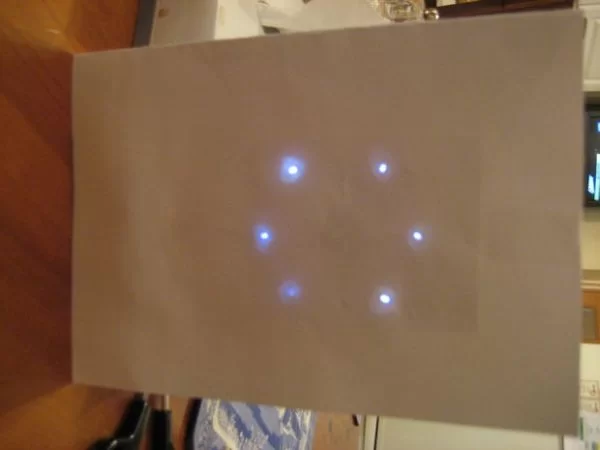
This is an instructable on how to build an LED Christmas card using the PIC 10F200 microcontroller.
As this PIC has six pins and is the size of an SMD transistor, it is ideal for low profile applications and can easily be reprogrammed as and when needed.
In this case I am using the “reverse polarised LED” trick to get six LED’s working from three I/O lines, as detailed in Microchip’s “Application Notes”.
Runs on two 3V cells, as the PIC’s maximum voltage is around 7V this is acceptable and the cells last a lot longer this way.
can be used with any of the 10F20x series but you may need to modify the code slightly.
Have fun, -Andre
Step 1: Program the PIC(s)
I’ve used the K182 programmer here, in order to make prototyping easier I soldered a 10F200 to a carrier PCB (cut down from inside an old Sony battery pack) and then soldered wires to this.
Note that this PIC requires ICSP, which means if your programmer doesen’t support this then you will need to find one that does. External 5V is needed, here it is provided from a 9V battery and 7805 regulator.
Step 2: Wire up the PICs
Having programmed the PICs, you will now need to connect them to the wires. I used the individual strands from some cable for this (about 30ga), and first tinned the PIC’s leads, then soldered a wire to each pin. A pair of tweezers with a locking function is very useful for this, as you can hold the PIC securely while soldering.
Its also possible to program the PICs once they are soldered in this way.
You will need a prototyping board and some component leads for this step, wind the wire(s) round the component leads and connect to the correct leads on the programmer.
For more detail: LED Christmas Cards using PIC 10F200

