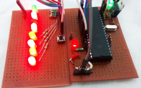
In our previous tutorial, we learnt about Blinking a LED using PIC microcontroller and built the same circuit on Perf board. Then we used PICkit 3, ICSP and MPLAB IPE for dumping the program onto our Perf board. Now, in this tutorial we will advance our self to using more pins on the PIC microcontroller. We will use 7 outputs (LEDs) and one Input. For this tutorial we will use the old Perf board (shown below) and will add berg sticks to pull out the required pins onto the second LED board. At the end of this tutorial we will Generate a Sequence of Blinking LEDs using PIC microcontroller and will learn how to use multiple inputs and outputs, some basics on ‘for’ loop and function calling.
Code and Working Explanation:
Complete Code has been given below (check at the end), here we will get it through line by line. This code will start to glow LEDs in a sequential manner when the push button is pressed. In order to understand the sequences please watch the video at the end of the tutorial. I would recommend you to compare the output shown in video with the code below and try to understand the program.
Let’s look at the code line by line. The first few lines are for setting up configuration bits which were explained in the previous tutorial so I am skipping them for now. The best way to understand any program is to start from the main (void main ()) function, so let’s do that
TRISB0=1; //Instruct the MCU that the PORTB pin 0 is used as input for button.
TRISD = 0x00; //Instruct the MCU that all pins are output
PORTD=0x00; //Initialize all pins to 0
The word TRIS is used to define if the pin is being used as input/output and the word PORT is used to make a pin High/Low. The line TRISB0=1 will make the 0th pin of PORT B as input. This will be our pushbutton. The lines TRISD = 0x00; PORTD=0x00; will make all the pins of port D as Output and assign a initial value of LOW to those pins.
Since we said that B0 is used as input, we will connect one end of the pushbutton to the pin B0 and other end to the ground. By then whenever we press the button the pin will be held to ground as shown in the connection diagram above. But to make this happen we have to use a pull up resistor so that the pin will be held high when the button is not pressed. A pull up resistor is something like this.
For more detail: LED Blinking Sequence using PIC Microcontroller