Summary of Interfacing PIC16F877A with DHT22(AM2302-RHT03) sensor using CCS PIC C
This article details the hardware and software implementation for interfacing a PIC16F877A microcontroller with a DHT22 (AM2302/RHT03) temperature and humidity sensor. It includes a circuit schematic, CCS C source code using version 5.051, and a Proteus simulation reference. The system reads sensor data, validates it via checksums, and displays results on a 1602 LCD, handling errors like timeouts or communication failures.
Parts used in the Interfacing PIC16F877A with DHT22 Project:
- PIC16F877A microcontroller
- DHT22 sensor (AM2302-RHT03)
- 1602 LCD display
- CCS PIC C compiler PCWHD version 5.051
- Proteus simulation environment
Interfacing PIC16F877A with DHT22(AM2302-RHT03) digital humidity and temperature sensor
This topic shows how to interface PIC16F877A microcontroller with DHT22 sensor with hardware circuit.
Related topic:
The following topic shows PIC16F877A microcontroller and DHT22 Proteus simulation and some details about this sensor.
PIC16F877A and DHT22(AM2302, RHT03) sensor Proteus simulation
Interfacing PIC16F877A with DHT22(AM2302, RHT03) sensor circuit:
The following circuit schematic shows complete project circuit.

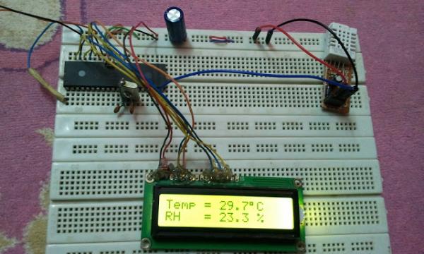
The circuit is simple, there is the microcontroller PIC16F877A, DHT22 sensor and 1602 LCD to display humidity and temperature results.
Interfacing PIC16F877A with DHT22(AM2302, RHT03) sensor CCS C code:
The interfacing code is written with CCS PIC C compiler PCWHD version 5.051.
If you want to understand the code please read the DHT22 datasheet.
Interfacing PIC16F877A with DHT22(AM2302, RHT03) sensor CCS C code:
The interfacing code is written with CCS PIC C compiler PCWHD version 5.051.
If you want to understand the code please read the DHT22 datasheet.
Variables Time_out and k are used to test reading time to avoid wrong data reception or microcontroller hanging.
// Interfacing PIC16F877A with DHT22(AM2302-RHT03) sensor CCS C code
// http://ccspicc.blogspot.com/
// [email protected]

//LCD module connections
#define LCD_RS_PIN PIN_B0
#define LCD_RW_PIN PIN_B1
#define LCD_ENABLE_PIN PIN_B2
#define LCD_DATA4 PIN_B3
#define LCD_DATA5 PIN_B4
#define LCD_DATA6 PIN_B5
#define LCD_DATA7 PIN_B6
//End LCD module connections

#include <16F877A.h>
#fuses HS,NOWDT,NOPROTECT,NOLVP
#use delay(clock = 8000000)
#include <lcd.c>
#use fast_io(D)
// Connection pin between PIC16F877A and DHT22 sensor
#BIT Data_Pin = 0x08.0                       // Pin mapped to PORTD.0
#BIT Data_Pin_Direction = 0x88.0             // Pin direction mapped to TRISD.0

char message1[] = "Temp = 00.0 C";
char message2[] = "RH   = 00.0 %";
short Time_out ;
unsigned int8 T_byte1, T_byte2, RH_byte1, RH_byte2, CheckSum ;
unsigned int16 Temp, RH;
void start_signal(){
  Data_Pin_Direction = 0;              // Configure connection pin as output
  Data_Pin = 0;                        // Connection pin output low
  delay_ms(25);
  Data_Pin = 1;                        // Connection pin output high
  delay_us(30);
  Data_Pin_Direction = 1;              // Configure connection pin as input
}
short check_response(){
  delay_us(40);
  if(!Data_Pin){                     // Read and test if connection pin is low
    delay_us(80);
    if(Data_Pin){                    // Read and test if connection pin is high
      delay_us(50);
      return 1;}
    }
}
unsigned int8 Read_Data(){
  unsigned int8 i, k, _data = 0;     // k is used to count 1 bit reading duration
  if(Time_out)
    break;
  for(i = 0; i < 8; i++){
    k = 0;
    while(!Data_Pin){                          // Wait until pin goes high
      k++;
      if (k > 100) {Time_out = 1; break;}
      delay_us(1);}
    delay_us(30);
    if(!Data_Pin)
      bit_clear(_data, (7 - i));               // Clear bit (7 - i)
    else{
      bit_set(_data, (7 - i));                 // Set bit (7 - i)
      while(Data_Pin){                         // Wait until pin goes low
      k++;
      if (k > 100) {Time_out = 1; break;}
      delay_us(1);}
    }
  }
  return _data;
}
void main(){
  lcd_init();                                 // Initialize LCD module
  lcd_putc('\f');                             // LCD clear
  while(TRUE){
    delay_ms(1000);
    Time_out = 0;
    Start_signal();
    if(check_response()){                    // If there is response from sensor
      RH_byte1 = Read_Data();                 // read RH byte1
      RH_byte2 = Read_Data();                 // read RH byte2
      T_byte1 = Read_Data();                  // read T byte1
      T_byte2 = Read_Data();                  // read T byte2
      Checksum = Read_Data();                 // read checksum
      if(Time_out){                           // If reading takes long time
        lcd_putc('\f');                       // LCD clear
        lcd_gotoxy(5, 1);                     // Go to column 5 row 1
        lcd_putc("Time out!");
      }
      else{
       if(CheckSum == ((RH_Byte1 + RH_Byte2 + T_Byte1 + T_Byte2) & 0xFF)){
        RH = RH_byte1;
        RH = (RH << 8) | RH_byte2;
        Temp = T_byte1;
        Temp = (Temp << 8) | T_byte2;
        if (Temp > 0X8000){
         message1[6] = '-';
         Temp = Temp & 0X7FFF; }
        else
         message1[6] = ' ';
        message1[7]  = (Temp / 100) % 10  + 48;
        message1[8]  = (Temp / 10) % 10  + 48;
        message1[10] = Temp % 10  + 48;
        message2[7]  = (RH / 100) % 10 + 48;
        message2[8]  = (RH / 10) % 10 + 48;
        message2[10] = RH % 10 + 48;
        message1[11] = 223;                   // Degree symbol
        lcd_putc('\f');                       // LCD clear
        lcd_gotoxy(1, 1);                     // Go to column 1 row 1
        printf(lcd_putc, message1);           // Display message1
        lcd_gotoxy(1, 2);                     // Go to column 1 row 2
        printf(lcd_putc, message2);           // Display message2
       }
        else {
          lcd_putc('\f');                     // LCD clear
          lcd_gotoxy(1, 1);                   // Go to column 1 row 1
          lcd_putc("Checksum Error!");
        }
      }
    }
    else {
      lcd_putc('\f');             // LCD clear
      lcd_gotoxy(3, 1);           // Go to column 3 row 1
      lcd_putc("No response");
      lcd_gotoxy(1, 2);           // Go to column 1 row 2
      lcd_putc("from the sensor");
    }
  }
}
Interfacing PIC16F877A with DHT22 sensor video:
The following video shows hardware circuit of this project.
- What components are required for this project?
The project uses a PIC16F877A microcontroller, a DHT22 sensor, and a 1602 LCD. - Which compiler is used for the code?
The code is written with CCS PIC C compiler PCWHD version 5.051. - How does the system handle reading errors?
The code uses variables Time_out and k to test reading time and avoid wrong data or hanging. - What happens if the checksum fails?
If the checksum does not match the sum of the data bytes, the LCD displays Checksum Error! - Can I view a video demonstration of the circuit?
Yes, a video showing the hardware circuit is available via the provided YouTube link. - Where can I find the Proteus simulation details?
Details about the Proteus simulation are mentioned in a related topic section. - How is negative temperature handled in the code?
If the temperature value exceeds 0X8000, a minus sign is added and the value is adjusted. - What pins are used for the LCD connections?
LCD connections use PORTB pins B0 through B6 for RS, RW, Enable, and data lines.