Summary of Interfacing 74HC595 Serial Shift Register with PIC Microcontroller
This article explains how to expand microcontroller I/O pins using a 74HC595 shift register, which converts serial input to parallel output. Using a PIC16F877A, the project connects three control pins to drive eight LEDs sequentially. The guide details the hardware setup, including resistors and capacitors, and provides C code for bit manipulation to light LEDs one by one or all at once, effectively solving pin shortage issues in embedded designs.
Parts used in the PIC16F877A Shift Register Project:
- PIC16F877A
- 2pcs 33pF ceramic disc capacitors
- 20Mhz Crystal
- 4.7k resistor
- 8pcs LEDs
- 1k resistor
- 74HC595 ic
- 5V wall adapter
- PIC programming environment
- Breadboard and wires
There are possibilities in embedded design where you do not have enough I/O pins available in your microcontroller. That can be due to any reason, may be your application needs multiple LEDs or you want to use multiple 7-segment displays, but you don’t have required I/O pins in your microcontroller. Here comes a perfect component, shift register. Shift register accepts serial data and give parallel output. It’s requires only 3 pins to connect with your microcontroller and you will get more than 8 Output pins from it. One of the popular shift register is 74HC595. It has 8 bit storage register and 8 bit shift register. Learn more about shift registers here.
You will provide serial data to the shift register and it will be latched on the storage register and then the storage register will control the 8 outputs. If you want more output just add another shift register. By cascading two shift registers, you will get additional 8 outputs, total 16bit output.
Shift Register 74HC595:
Here is the pin out diagram of the 74HC595 as per the datasheet-
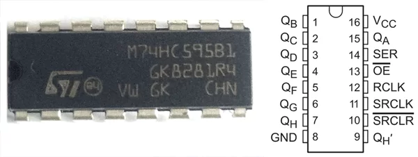
HC595 has 16pins; if we see the datasheet we will understand the pin functions-
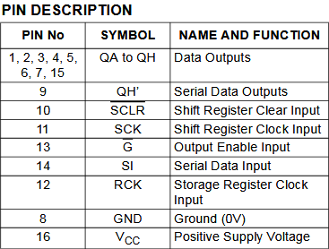
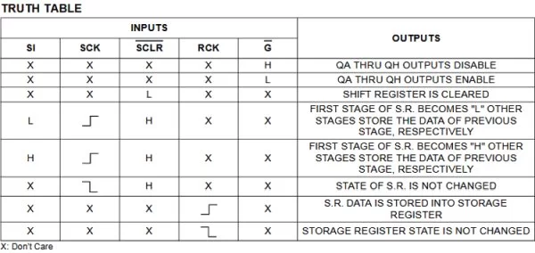
The QA to QH, from pin numbers 1 to 7 and 15 used as 8 bit output from the shift register, where as the pin 14 is used for receiving the serial data. There is also truth table about how to use other pins and avail other functions of the shift register.
Components Required:
- PIC16F877A
- 2pcs 33pF ceramic disc capacitors
- 20Mhz Crystal
- 4.7k resistor
- 8pcs LEDs
- 1k resistor -1 pc (8 pcs 1k resistors required if separate resistors on each leds needed)
- 74HC595 ic
- 5V wall adapter
- PIC programming environment
- Breadboard and wires
Circuit Diagram:
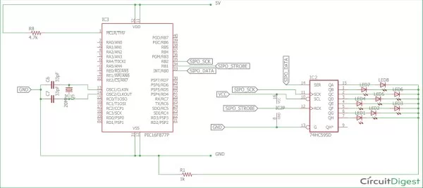
In circuit diagram, we have connected the serial data pin; clock and strobe (latch) pin on microcontroller’s RB0, RB1 and RB2 pin respectively. Here we have used one resistor for 8 LEDs. As per the truth table, we enabled output by connecting the pin 13 of 74HC595 to ground. The QH pin is left open as we will not cascade another 74HC595 with it. We disabled the clear input flag by connecting pin 10 of the shift register with VCC.
The Crystal oscillator is connected on the OSC pins of the microcontroller. PIC16F877A do not have any internal oscillator. In this project we will light up the led one by one from Q0 to Q7 using shift regitster.
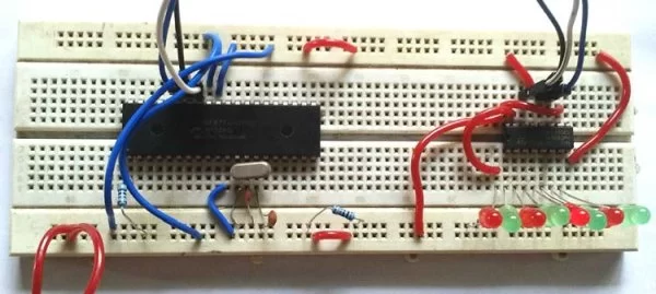
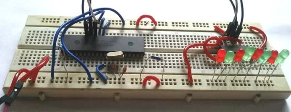
We have constructed the circuit in a breadboard-
Code Explanation:
Complete code for controlling LEDs with shift register is given at the end of article. As always, we need to set the configuration bits in the PIC microcontroller.
#pragma config FOSC = HS        // Oscillator Selection bits (HS oscillator)
#pragma config WDTE = OFF       // Watchdog Timer Enable bit (WDT disabled)
#pragma config PWRTE = OFF      // Power-up Timer Enable bit (PWRT disabled)
#pragma config BOREN = ON       // Brown-out Reset Enable bit (BOR enabled)
#pragma config LVP = OFF         // Low-Voltage (Single-Supply) In-Circuit Serial Programming Enable bit (RB3/PGM pin has PGM function; low-voltage programming enabled)
#pragma config CPD = OFF        // Data EEPROM Memory Code Protection bit (Data EEPROM code protection off)
#pragma config WRT = OFF        // Flash Program Memory Write Enable bits (Write protection off; all program memory may be written to by EECON control)
#pragma config CP = OFF         // Flash Program Memory Code Protection bit (Code protection off)
After that we declared the crystal frequency which is required for the delay and the pin-out declaration for 74HC595.
#include <xc.h>
/*
 Hardware related definition
 */
#define _XTAL_FREQ 20000000 //Crystal Frequency, used in delay
#define DATA_595 PORTBbits.RB0
#define STROBE_595 PORTBbits.RB1
#define CLK_595 PORTBbits.RB2
Next we declared system_init() function to initialize the pin direction.
void system_init(void){
    TRISB = 0x00;
    }
We created the clock pulse and latch pulse using two different functions
/*
 *This function will enable the Clock.
 */
void clock(void){
    CLK_595 = 1;
    __delay_us(500);
    CLK_595 = 0;
    __delay_us(500);
}
and
/*
 *This function will strobe and enable the output trigger.
 */

void strobe(void){
    STROBE_595 = 1;
    __delay_us(500);
    STROBE_595 = 0;
    }
After this two functions we declared the data_submit(unsigned int data) function to submit serial data to the 74HC595.
void data_submit(unsigned int data){
    for (int i=0 ; i<8 ; i++){
        DATA_595 = (data >> i) & 0x01;
        clock();
    }
    strobe(); // Data finally submitted
}
In this function we accept 8bit data and send each bit using two bitwise operators left shift and AND operator. We first shift the data one by one and find out the exact bit whether it is 0 or 1 using AND operator with 0x01. Each data is stored by the clock pulse and final data output done using the latch or strobe pulse. In this process the data output will be MSB (Most Significant Bit) first.
In the main function we submitted the binary and made the output pins high one by one.
    system_init(); // System getting ready
    while(1){
        data_submit(0b00000000);
        __delay_ms(200);
        data_submit(0b10000000);
        __delay_ms(200);
        data_submit(0b01000000);
        __delay_ms(200);
        data_submit(0b00100000);
        __delay_ms(200);
        data_submit(0b00010000);
        __delay_ms(200);
        data_submit(0b00001000);
        __delay_ms(200);
        data_submit(0b00000100);
        __delay_ms(200);
        data_submit(0b00000010);
        __delay_ms(200);
        data_submit(0b00000001);
        __delay_ms(200);
        data_submit(0xFF);
        __delay_ms(200);
     }
    return;
    }
That is how a shift register can be used to get more free I/O pins in any microcontroller for connecting more sensors.
/*
* File: main.c
* Author: Sourav Gupta
* By:- circuitdigest.com
* Created on May 30, 2018, 2:26 PM
*/
// PIC16F877A Configuration Bit Settings
// ‘C’ source line config statements
// CONFIG
#pragma config FOSC = HS // Oscillator Selection bits (HS oscillator)
#pragma config WDTE = OFF // Watchdog Timer Enable bit (WDT disabled)
#pragma config PWRTE = OFF // Power-up Timer Enable bit (PWRT disabled)
#pragma config BOREN = ON // Brown-out Reset Enable bit (BOR enabled)
#pragma config LVP = OFF // Low-Voltage (Single-Supply) In-Circuit Serial Programming Enable bit (RB3/PGM pin has PGM function; low-voltage programming enabled)
#pragma config CPD = OFF // Data EEPROM Memory Code Protection bit (Data EEPROM code protection off)
#pragma config WRT = OFF // Flash Program Memory Write Enable bits (Write protection off; all program memory may be written to by EECON control)
#pragma config CP = OFF // Flash Program Memory Code Protection bit (Code protection off)
#include <xc.h>
/*
Hardware related definition
*/
#define _XTAL_FREQ 20000000 //Crystal Frequency, used in delay
#define DATA_595 PORTBbits.RB0
#define STROBE_595 PORTBbits.RB1
#define CLK_595 PORTBbits.RB2
#define LED PORTBbits.RB3
/*
Other Specific definition
*/
void system_init(void);
/*
*This function will enable the Clock.
*/
void clock(void){
CLK_595 = 1;
__delay_us(500);
CLK_595 = 0;
__delay_us(500);
}
/*
*This function will strobe and enable the output trigger.
*/
void strobe(void){
STROBE_595 = 1;
__delay_us(500);
STROBE_595 = 0;
}
/*
* This function will send the data to shift register
*/
void data_submit(unsigned int data){
for (int i=0 ; i<8 ; i++){
DATA_595 = (data >> i) & 0x01;
clock();
}
strobe(); // Data finally submitted
}
void main(void) {
system_init(); // System getting ready
while(1){
data_submit(0b00000000);
__delay_ms(200);
data_submit(0b10000000);
__delay_ms(200);
data_submit(0b01000000);
__delay_ms(200);
data_submit(0b00100000);
__delay_ms(200);
data_submit(0b00010000);
__delay_ms(200);
data_submit(0b00001000);
__delay_ms(200);
data_submit(0b00000100);
__delay_ms(200);
data_submit(0b00000010);
__delay_ms(200);
data_submit(0b00000001);
__delay_ms(200);
data_submit(0xFF);
__delay_ms(200);
}
return;
}
/*
This Function is for system initialisations.
*/
void system_init(void){
TRISB = 0x00;
}
Read more detail:Interfacing 74HC595 Serial Shift Register with PIC Microcontroller
- How many pins does the 74HC595 require to connect with a microcontroller?
The 74HC595 requires only 3 pins to connect with your microcontroller. - What is the primary function of the 74HC595 shift register?
It accepts serial data and gives parallel output, providing more than 8 Output pins from just 3 connections. - Can you cascade two shift registers to get more outputs?
Yes, by cascading two shift registers, you will get additional 8 outputs for a total of 16bit output. - Which pins on the PIC16F877A are connected to the shift register?
The serial data, clock, and strobe pins are connected to microcontroller's RB0, RB1, and RB2 pins respectively. - Why is pin 13 of the 74HC595 connected to ground?
Connecting pin 13 to ground enables the output according to the truth table. - What happens if pin 10 of the shift register is not connected to VCC?
Pin 10 must be connected to VCC to disable the clear input flag. - Does the PIC16F877A have an internal oscillator?
No, the PIC16F877A does not have any internal oscillator, so an external crystal is required. - How does the data_submit function send bits to the shift register?
It shifts the data one by one using bitwise operators and sends each bit using a clock pulse before finally submitting the data with a latch pulse. - What is the order of data output in this project?
In this process, the data output will be MSB (Most Significant Bit) first. - How can you light up all LEDs simultaneously?
You can submit the binary value FF to the data_submit function to light up all LEDs.