Summary of Gas Detection and PPM Measurement using PIC Microcontroller and MQ Gas Sensors
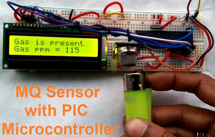
This article details a project to detect LPG gas concentration using an MQ6 sensor interfaced with a PIC16F877A microcontroller. The system measures gas in PPM, displays the value on a 16x2 LCD, and indicates gas presence via a digital pin. The process involves calibrating the sensor in clean air, calculating resistance ratios, and applying a logarithmic curve formula derived from the datasheet to determine accurate PPM values.
Parts used in the Gas Detection and PPM Measurement Project:
- 5V power supply
- Breadboard
- 4.7k resistor
- LCD 16x2
- 1k resistor
- 20Mhz crystal
- 33pF capacitor - 2pcs
- PIC16F877A microcontroller
- MQ series sensor (specifically MQ6)
- Berg and other hookup wires
MQ series Gas sensors are very common types of sensors used in Gas Detectors to detect or measure certain types of Gases. These sensors are widely used in all Gas related devices like from simple Smoke Detectors to Industrial Air Quality Monitors. We have already used these MQ gas sensors with Arduino to measure some harmful gases like Ammonia. In this article, we will learn how to use these gas sensors with PIC Microcontrollers, to measure the PPM value of the gas and display it on a 16×2 LCD.
As mentioned earlier, there are different kinds of MQ series sensors available in the market and each sensor can measure different types of gases as shown in the table below. For the sake of this article, we will be using the MQ6 Gas sensor with PIC that can be used to detect the LPG gas presence and concentration. However, by using the same hardware and firmware other MQ series sensors can also be used without major modification in the code and hardware part.
| Sensor | Detects |
| MQ-2 | Methane, Butane, LPG, smoke |
| MQ-3 | Alcohol, Ethanol, smoke |
| MQ-4 | Methane, CNG Gas |
| MQ-5 | Natural gas, LPG |
| MQ-6 | LPG, butane gas |
| MQ-7 | Carbon Monoxide |
| MQ-8 | Hydrogen Gas |
| MQ-9 | Carbon Monoxide, flammable gasses. |
| MQ131 | Ozone |
| MQ135 | Air Quality (Benzene, Alcohol, smoke) |
| MQ136 | Hydrogen Sulfide gas |
| MQ137 | Ammonia |
| MQ138 | Benzene, Toluene, Alcohol, Acetone, Propane, Formaldehyde gas, Hydrogen |
| MQ214 | Methane, Natural gas |
| MQ216 | Natural gas, Coal gas |
| MQ303A | Alcohol, Ethanol, smoke |
| MQ306A | LPG, butane gas |
| MQ307A | Carbon Monoxide |
| MQ309A | Carbon Monoxide, flammable gasses |
| MG811 | Carbon Dioxide (CO2) |
| AQ-104 | Air quality |
MQ6 Gas Sensor
The below image shows the MQ6 sensor pin diagram. However, the left image is a module-based MQ6 sensor for interfacing with the microcontroller unit, the pin diagram of the module is also shown in that image.
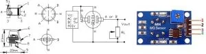
Pin 1 is VCC, Pin 2 is the GND, Pin 3 is the Digital out (Logic low when gas is detected.) and Pin 4 is the Analog output. The pot is used to adjust the sensitivity. It is not RL. The RL resistor is the right resistor of the DOUT LED.
Each MQ series sensor has a heating element and a sensing resistance. Depending on the concentration of the gas, the sensing resistance gets changed and by detecting the changing resistance, the gas concentration can be measured. To measure the gas concentration in PPM all MQ sensors provide a logarithmic graph which is very important. The graph provides an overview of the gas concentration with the ratio of RS and RO.
How to measure PPM using MQ Gas sensors?
The RS is the sense resistance during the presence of a particular gas whereas the RO is the sense resistance in clean air without any particular gas. The below logarithmic graph taken from the datasheet provides an overview of the gas concentration with the sense resistance of the MQ6 sensor. The MQ6 sensor is used to detect LPG gas concentration. Therefore, the MQ6 sensor will provide a particular resistance during the clean air condition where the LPG gas is unavailable. Also, the resistance will change whenever the LPG gas is detected by the MQ6 sensor.
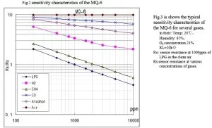
So, we need to plot this graph into our firmware similar to what we did in our Arduino Gas detector Project. The formula is to have 3 different data points. The first two data points are the starting of the LPG curve, in X and Y coordinates. The third data is the slope.
So, If we select the deep blue curve which is the LPG curve, the starting of the curve in X and Y coordinate is the 200 and 2. So, the first data point from the logarithmic scale is (log200, log2) which is (2.3, 0.30).
Let’s make it as, X1 and Y1 = (2.3, 0.30). The ending of the curve is the second data point. By the same process described above, X2 and Y2 are (log 10000, log0.4). Thus, X2 and Y2 = (4, -0.40). To get the slope of the curve, the formula is
=(Y2-Y1)/(X2-X1)
=(-0.40 - 0.30) / (4 - 2.3)
= (-0.70) / (1.7)
= -0.41
The graph we need can be given as
LPG_Curve = {starting X and starting Y, slope}

 LPG_Curve = {2.3, 0.30, -0.41}
For other MQ sensors, get the above data from the datasheet and the Logarithmic graph plot. The value will differ based on the sensor and gas measured. For this particular module, it has a digital pin that only provides information about gas present or not. For this project, it is also used.
Required components
The required components for interfacing MQ sensor with PIC microcontroller are given below-
- 5V power supply
- Breadboard
- 4.7k resistor
- LCD 16×2
- 1k resistor
- 20Mhz crystal
- 33pF capacitor – 2pcs
- PIC16F877A microcontroller
- MQ series sensor
- Berg and other hookup wires.
Schematic
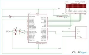
The schematic for this Gas sensor with a PIC project is pretty straight forward. The Analog pin is connected with the RA0 and the digital one with the RD5 to measure the analog voltage provided by the Gas sensor module. If you are completely new to PIC, then you might want to look into PIC ADC tutorial and PIC LCD tutorial to better understand this project.
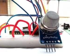
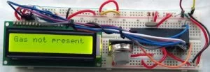
The circuit is constructed in a breadboard. Once the connections were completed, my set-up looks like this, shown below.
The main part of this code is the main function and other associated peripheral functions. The Complete program can be found at the bottom of this page, the important code snippets are explained as follows
The below function is used for getting the sensor resistance value in free air. As the Analog channel 0 is used, it is getting data from the analog channel 0. This is for calibrating the MQ Gas sensor.
float SensorCalibration(){
  int count;                                              // This function will calibrate the sensor in free air
  float val=0;
  for (count=0;count<50;count++) {                   //take multiple samples and calculate the average value
                val += calculate_resistance(ADC_Read(0));
                __delay_ms(500);
  }
  val = val/50;
  val = val/RO_VALUE_CLEAN_AIR;                              //divided by RO_CLEAN_AIR_FACTOR yields the Ro
  return val;
}
Below Function is used to read the MQ sensor analog values and average it to calculate the Rs value
float read_MQ()
{
  int count;
  float rs=0;
  for (count=0;count<5;count++) { // take multiple readings and average it.
                rs += calculate_resistance(ADC_Read(0));   // rs changes according to gas concentration.
                __delay_ms(50);
  }
  rs = rs/5;

  return rs;
}
The below function is used to calculate the resistance from the voltage divider resistor and the load resistance.
float calculate_resistance(int adc_channel)
{                                                               // sensor and load resistor forms a voltage divider. so using analog value and load value
  return ( ((float)RL_VALUE*(1023-adc_channel)/adc_channel));            // we will find sensor resistor.
}
The RL_VALUE is defined at the starting of the code like shown below
#define RL_VALUE (10) //define the load resistance on the board, in kilo-ohms
Change this value after checking the onboard load resistance. It can be different in other MQ sensor boards. To plot the available data into the log scale, the below function is used.
int gas_plot_log_scale(float rs_ro_ratio, float *curve)
{
                return pow(10,(((log(rs_ro_ratio)-curve[1])/curve[2]) + curve[0]));
}
The curve is the LPG curve defined in above of the code that is previously calculated in our article above.
float MQ6_curve[3] = {2.3,0.30,-0.41}; //Graph Plot, change this for particular sensor
Finally, the main function inside which we measure the analog value, calculate the PPM and display it on the LCD is given below
void main() {
                system_init();
                clear_screen();
                lcd_com(FIRST_LINE);
                lcd_puts("Calibrating....");
                Ro = SensorCalibration();
                //clear_screen();
                lcd_com(FIRST_LINE);
                lcd_puts("Done!                   ");
                //clear_screen();
                lcd_com(FIRST_LINE);                 lcd_print_number(Ro);
                lcd_puts(" K Ohms");
                __delay_ms(1500);
                gas_detect = 0;
 while(1){
                if(gas_detect == 0){
                lcd_com(FIRST_LINE);
                lcd_puts("Gas is present  ");
                lcd_com(SECOND_LINE);
                lcd_puts ("Gas ppm = ");
                float rs = read_MQ();
                float ratio = rs/Ro;
                lcd_print_number(gas_plot_log_scale(ratio, MQ6_curve));
                __delay_ms(1500);
                clear_screen();
                }
                else{
                lcd_com(FIRST_LINE);
                lcd_puts("Gas not present  ");
                }
                }
}
First, the sensor’s RO is measured in clean air. Then the digital pin is read to check whether the gas is present or not. If the gas is present, the gas is measured by the provided LPG curve.
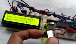
I have used a lighter to check if the PPM value is changing when the gas is detected. These cigar lighters have LPG gas inside them, which when released in the air will be read by our sensor and the PPM value on the LCD changes as shown below.
The complete working can be found in the video given at the bottom of this page. If you have any questions please leave them in the comment section, or use our forums for other technical questions.
#include <stdint.h>
#include <math.h>
#include “supporing_cfile/lcd.h”
#include “supporing_cfile/adc.h”
#pragma config FOSC = HS // Oscillator Selection bits (HS oscillator)
#pragma config WDTE = OFF // Watchdog Timer Enable bit (WDT disabled)
#pragma config PWRTE = ON // Power-up Timer Enable bit (PWRT enabled)
#pragma config BOREN = ON // Brown-out Reset Enable bit (BOR enabled)
#pragma config LVP = OFF // Low-Voltage (Single-Supply) In-Circuit Serial Programming Enable bit (RB3 is digital I/O, HV on MCLR must be used for programming)
#pragma config CPD = OFF // Data EEPROM Memory Code Protection bit (Data EEPROM code protection off)
#pragma config WRT = OFF // Flash Program Memory Write Enable bits (Write protection off; all program memory may be written to by EECON control)
#pragma config CP = OFF // Flash Program Memory Code Protection bit (Code protection off)
/*
Program Flow related definition
*/
#define gas_detect PORTDbits.RD5
#define gas_Detect_Pin_Direction TRISDbits.TRISD5
#define FIRST_LINE 0x80
#define SECOND_LINE 0xC0
#define RL_VALUE (10) //define the load resistance on the board, in kilo ohms
#define RO_VALUE_CLEAN_AIR (9.83) //(Sensor resistance in clean air)/RO,
//which is derived from the chart in datasheet
float MQ6_curve[3] = {2.3,0.30,-0.41}; //two points from LPG curve are taken point1:(200,1.6) point2(10000,0.26)
//take log of each point (lg200, lg 1.6)=(2.3,0.20) (lg10000,lg0.26)=(4,-0.58)
//find the slope using these points. take point1 as reference
//data format:{ x, y, slope};
float Ro = 0; //Ro is initialized to 10 kilo ohms
#define _XTAL_FREQ 20000000 //20 Mhz
// System related definitions
void system_init(void);
void introduction_screen(void);
void clear_screen(void);
//int GetPercentage(float rs_ro_ratio, float *pcurve);
int gas_plot_log_scale(float rs_ro_ratio, float *curve);
float read_mq();
float calculate_resistance(int raw_adc);
float SensorCalibration();
void main() {
system_init();
clear_screen();
lcd_com(FIRST_LINE);
lcd_puts(“Calibrating….”);
Ro = SensorCalibration();
//clear_screen();
lcd_com(FIRST_LINE);
lcd_puts(“Done! “);
//clear_screen();
lcd_com(FIRST_LINE);
lcd_print_number(Ro);
lcd_puts(” K Ohms”);
__delay_ms(1500);
gas_detect = 0;
while(1){
if(gas_detect == 0){
lcd_com(FIRST_LINE);
lcd_puts(“Gas is present “);
lcd_com(SECOND_LINE);
lcd_puts (“Gas ppm = “);
float rs = read_mq();
float ratio = rs/Ro;
lcd_print_number(gas_plot_log_scale(ratio, MQ6_curve));
__delay_ms(1500);
clear_screen();
}
else{
lcd_com(FIRST_LINE);
lcd_puts(“Gas not present “);
//lcd_com(SECOND_LINE);
// lcd_print_number(gas_plot_log_scale(read_mq()/Ro, MQ6_curve));
}
}
}
void system_init(){
TRISB = 0; // LCD pins set to out.
gas_Detect_Pin_Direction = 1; //Configure RD0 as input
lcd_init();
ADC_Init();
introduction_screen();
//dht11_init();
}
/*
This Function is for Clear screen without command.
*/
void clear_screen(void){
lcd_com(FIRST_LINE);
lcd_puts(” “);
lcd_com(SECOND_LINE);
lcd_puts(” “);
}
/*
This Function is for playing introduction.
*/
void introduction_screen(void){
lcd_com(FIRST_LINE);
lcd_puts(“Welcome to”);
lcd_com(SECOND_LINE);
lcd_puts(“circuit Digest”);
__delay_ms(1000);
__delay_ms(1000);
clear_screen();
lcd_com(FIRST_LINE);
lcd_puts(“MQ6 Sensor”);
lcd_com(SECOND_LINE);
lcd_puts(“with PIC16F877A”);
__delay_ms(1000);
__delay_ms(1000);
}
/*
* Sensor Related Functions
*/
float SensorCalibration(){
int count; // This function assumes that sensor is in clean air.
float val=0;
for (count=0;count<50;count++) { //take multiple samples and calculate the average value
val += calculate_resistance(ADC_Read(0));
__delay_ms(500);
}
val = val/50;
val = val/RO_VALUE_CLEAN_AIR; //divided by RO_CLEAN_AIR_FACTOR yields the Ro
//according to the chart in the datasheet
return val;
}
float read_mq()
{
int count;
float rs=0;
for (count=0;count<5;count++) { // take multiple readings and average it.
rs += calculate_resistance(ADC_Read(0)); // rs changes according to gas concentration.
__delay_ms(50);
}
rs = rs/5;
return rs;
}
float calculate_resistance(int adc_channel)
{ // sensor and load resistor forms a voltage divider. so using analog value and load value
return ( ((float)RL_VALUE*(1023-adc_channel)/adc_channel)); // we will find sensor resistor.
}
int gas_plot_log_scale(float rs_ro_ratio, float *curve)
{
return pow(10,(((log(rs_ro_ratio)-curve[1])/curve[2]) + curve[0]));
}
Source: Gas Detection and PPM Measurement using PIC Microcontroller and MQ Gas Sensors
- How do you measure gas concentration in PPM using MQ sensors?
You plot the logarithmic graph from the datasheet into firmware using two data points and a slope to calculate the ratio of sense resistance to clean air resistance. - Can different MQ series sensors be used with this hardware?
Yes, other MQ series sensors can be used with the same hardware and firmware without major modifications, provided the curve data is updated. - What is the function of the pot on the MQ6 module?
The pot is used to adjust the sensitivity of the sensor. - Which pins are connected to the PIC microcontroller for this project?
The analog pin connects to RA0 and the digital pin connects to RD5. - How is the sensor calibrated before measurement?
The sensor is calibrated by taking multiple samples in free air to calculate the average resistance value in clean air. - What does the digital output pin indicate?
The digital output provides logic low when gas is detected. - Why is the RL_VALUE important in the code?
The RL_VALUE defines the load resistance on the board in kilo-ohms and must match the actual onboard resistor to calculate resistance correctly. - How is the LPG curve defined in the firmware?
The curve is defined as an array containing the starting X coordinate, starting Y coordinate, and the calculated slope of the logarithmic graph.