Summary of Disco Lights Project using pic microcontoller
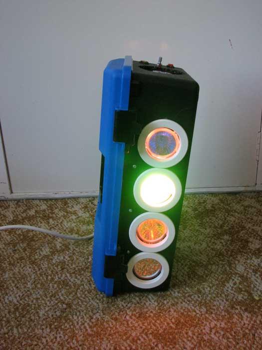
The Disco Lights project combines beat detection circuitry with colored halogen lamps to create flashing patterns synchronized with music. A microcontroller, specifically a PICAXE 18X, processes audio pulses to control four 50W 12V halogen lamps in red, yellow, green, and blue. The system uses a level-shifting transistor to interface the beat detection output with the microcontroller, which can be programmed via a PC using BASIC or flow charts.
Parts used in the Disco Lights:
- PICAXE 18X microcontroller
- Four 12V 50W colored halogen lamps (red, yellow, green, blue)
- Ceramic lamp holders
- MOSFETs for lamp control
- Transistor Q1 for level shifting
- Sensitivity potentiometer
- Push button switch S1
- LED indicators DS1 and DS2
- Vero-board for circuit assembly
- Serial port cable and resistors for programming
What does it do?
The Disco Lights project is what you get when you combine the fantastic beat detection circuitry of my ever popular beat triggered strobe light with coloured halogen lamps! In other words, four coloured lights flash in a variety of patterns in time with your music. Some seriously cool patterns can be achieved and the effect is really amazing!
Even better, the effects are achieved using a microcontroller, so you can program your own patterns and effects in fact you can even choose to use your own microcontroller that you are familiar with or if you’re not familiar with microcontrollers, you can use the one shown in my design which can be programmed in either basic or with a flow chart, all you need is a PC with a serial port an old mouse cable & a couple of resistors and you’re away!
 Circuit details
Most of the circuit is actually borrowed exactly from the low voltage section of the beat triggered strobe light. In fact, it would be possible to assemble half of the circuitry on the beat strobe’s circuit board, simply omitting the high voltage section and the opto isolator. Since I did not have any spare strobe boards and the circuit is relatively straight forward, I assembled it on vero-board. If you choose to take this route, just be very careful and check your work as I myself made a few errors along the way, it’s fairly easy with vero-board. Figure 1 shows the initial analogue processing. Yes it is almost verbatim from the beat strobe, the only differences being the supply voltages. For details on how it works, please check out the beat triggered strobe.
Note: Images with GREEN borders can be enlarged by double clicking on them and returned to original size by single clicking. You need javascript enabled for this to work. The original size should fit a 1024×768 monitor comfortably but might not be as clear.
Pulse shaping and flash rate limiting
The next section of the strobe circuit is the pulse shaping section. It is shown in figure 2 below and again is the same as what was used in the beat triggered strobe light, except that instead of an opto-isolator, we take the pulses off to a point marked A. I also left out S1 & R18 but it is a matter of personal preference. I have found the music triggering to be excellent, especially when the audio line input is used rather than the internal microphone.
Disco lights specific circuitry and microcontrollers
This is where the disco lights are different to the beat triggered strobe light. Instead of each beat triggering a high voltage xenon flash tube to create a bright white flash, it serves as a cue to a microcontroller to produce the next pattern on a set of coloured halogen lamps. These lamps are rated at 12V, 50W and came in red, yellow, green and blue. I purchased them from Jaycar Electronics, catalogue numbers SL2741-SL2744. I would urge that you also purchase some holders for these bulbs as they get rather hot so the proper ceramic bases are much less likely to cause a fire than any impromptue mounting solution and take it from me, the pins don’t solder well and it’s a pain to change bulbs if soldered to wires. 😉
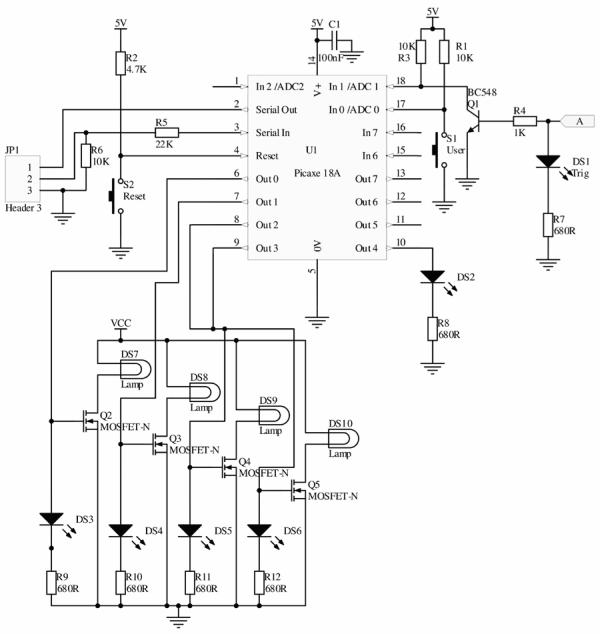
But back to the circuit. Figure 3 shows the rest of the circuit for the disco lights. Here, I have chosen to use a PICAXE microcontroller. These are an educational variation of the PIC microcontroller family and whilst they have several major limitations, the only one that is going to be a problem here is the memory capacity. For this reason, I reccomend that you use the PICAXE 18X rather than the 18A that I used here (which has been discontinued but it was the one in stock at my local electronics shop). They are pin compatible.
 You can of course use any microcontroller and I highly reccommend using one that you’re familiar with especially if it can be programmed in C as after a while, BASIC becomes a bit verbose for my liking at least. Details about the PICAXE can be found at www.picaxe.co.uk. You will also need to download the free software and make up a programming cable. They’re really easy to use, even if you’re new to microcontrollers (but know enough basic electronics to do the rest of the project). If you are experienced in the use PICs or ATMEGAs then you’d be better using those. I personally used a PICAXE so that I could give someone who’d never used a micro before a chance to write the code for me and the patterns were so cool that I continue to use his code. It can be downloaded at the bottom of this page. 🙂
The pulses from figure two come in on the right of figure 3 at the point marked A. These are then level shifted down from 9 volts to 5 volts by Q1 which also has the effect of inverting them. Thus, the microcontroller should be programmed to respond to a falling edge. S1 is a switch that I provided for manually changing patterns or otherwise interacting with the disco lights. Likewise, LED DS2 is next to this push button. I also placed LED DS1 next to the sensitivity pot from figure 1 on the panel to indicate triggering so that it can be adjusted more easily. Outputs 0 to 3 control the MOSFETs which in turn control the 50 Watt halogen lamps.
For more detail: Disco Lights Project
- How does the project synchronize lights with music?
The beat detection circuitry sends pulses to a microcontroller which triggers specific lighting patterns on colored halogen lamps. - Can I use a different microcontroller than the one specified?
Yes, you can use any microcontroller you are familiar with, such as a PIC or ATMEGA, provided it can handle the logic. - What is the recommended microcontroller model for this project?
The PICAXE 18X is recommended over the discontinued 18A due to better memory capacity. - Why should ceramic bases be used for the lamps?
Ceramic bases are safer because the lamps get very hot and improper mounting solutions could cause fires. - Does the microcontroller respond to rising or falling edges?
The microcontroller should be programmed to respond to a falling edge after the signal is inverted by transistor Q1. - What programming languages can be used for the microcontroller?
The PICAXE controller can be programmed in BASIC or using a flow chart interface. - How are the lamp outputs controlled in the circuit?
Outputs 0 to 3 on the microcontroller control MOSFETs which switch the power to the 50 Watt halogen lamps. - Is an internal microphone required for the audio input?
No, using an external audio line input provides excellent music triggering results compared to an internal microphone.