Summary of Digital Ammeter Circuit using PIC Microcontroller and ACS712
This project builds a digital ammeter using a PIC16F877A microcontroller and ACS712 current sensor to measure AC/DC currents (0–30 A possible) with about 0.3 A accuracy, displaying readings on a 16x2 LCD. The ACS712 provides isolated hall-effect sensing; its Vout is read by the PIC ADC (AN4), averaged over 20 samples to reduce noise, and converted to current using sensor sensitivity values (18.5 mV/A for 5A module, 0.66 mV/A for 30A).
Parts used in the Digital Ammeter Project:
- PIC16F877A microcontroller
- 7805 voltage regulator
- ACS712 current sensor (ACS712-5A or ACS712-30A)
- 16x2 LCD display
- Junction box and load (for testing)
- Connecting wires
- Capacitors
- Breadboard or perf board
- 12V power supply
Measuring the voltage and current will always be helpful while making or debugging any electrical system. In this project we are going to make our own Digital Ammeter using PIC16F877A Microcontroller and current sensor ACS712-5A. This project can measure both AC and DC current with a range of 0-30A with an accuracy of 0.3A. With few modifications on the code you can also use this circuit to measure up to 30A. So let us get started!!!
Materials Required:
- PIC16F877A
- 7805 Voltage Regulator
- ACS712 current Sensor
- 16*2 LCD display
- A junction box and load (Just for testing)
- Connecting wires
- Capacitors
- Breadboard.
- Power supply – 12V
Working of ACS712 Current Sensor:
Before we start building the project it is very important for us to understand the working of the ACS712 Current sensor as it is the key component of the project. Measuring current especially AC current is always a tough task due to the noise coupled with it improper isolation problem etc. But, with the help of this ACS712 module which was engineered by Allegro thing have become a lot easier.
This module works on the principle of Hall-effect, which was discovered by Dr. Edwin Hall. According his principle, when a current carrying conductor is placed into a magnetic field, a voltage is generated across its edges perpendicular to the directions of both the current and the magnetic field. Let us not get too deep into the concept but, simply put we use a hall sensor to measure the magnetic field around a current carrying conductor. This measurement will be in terms of millivolts which we called as the hall-voltage. This measured hall-voltage is proportional to the current that was flowing through the conductor.
The major advantage of using ACS712 Current Sensor is that is can measure both AC and DC current and it also provides isolation between the Load (AC/DC load) and Measuring Unit (Microcontroller part). As shown in the picture we have three pins on the module which are Vcc, Vout and Ground respectively.
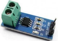
The 2-pin terminal block is where the current carrying wire should be passed through. The module work on +5V so the Vcc should be powered by 5V and the ground should be connected to Ground of the system. The Vout pin has an offset voltage of 2500mV, meaning when there is no current flowing through the wire then the output voltage will be 2500mV and when current flowing is positive, the voltage will be greater than 2500mV and when the current flowing is negative, the voltage will be less than 2500mV.
We will be using the ADC module of the PIC microcontroller to read the output voltage (Vout) of the module, which will be 512(2500mV) when there is no current flowing through the wire. This value will reduce as the current flows in negative direction and will increase as the current flows in positive direction. The below table will help you understand how the output voltage and ADC value varies based on the current flowing through the wire.
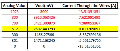
These values were calculated based on the information given in the Datasheet of ACS712. You can also calculate them using the below formulae:
Vout Voltage(mV) = (ADC Value/  1023)*5000
Current Through the Wire (A) = (Vout(mv)-2500)/185
Now, that we know how the ACS712 Sensor works and what we could expect from it. Let us proceed to the circuit diagram.
Circuit Diagram:
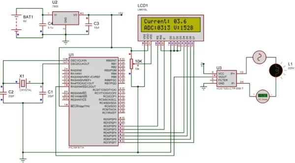
The complete circuit diagram of this Digital Ammeter Project is shown in the image below.
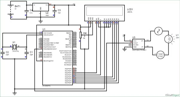
The complete digital current meter circuit works on +5V which is regulated by a 7805 Voltage regulator. We have used a 16X2 LCD to display the value of the current. The output pin of the current Sensor (Vout) is connected to the 7th pin of the PIC which is the AN4 to read the Analog voltage.
Further the pin connection for the PIC is shown in the table below
|
S.No: |
Pin Number |
Pin Name |
Connected to |
|
1 |
21 |
RD2 |
RS of LCD |
|
2 |
22 |
RD3 |
E of LCD |
|
3 |
27 |
RD4 |
D4 of LCD |
|
4 |
28 |
RD5 |
D5 of LCD |
|
5 |
29 |
RD6 |
D6 of LCD |
|
6 |
30 |
RD7 |
D7 of LCD |
|
7 |
7 |
AN4 |
Vout of Current Sesnor |
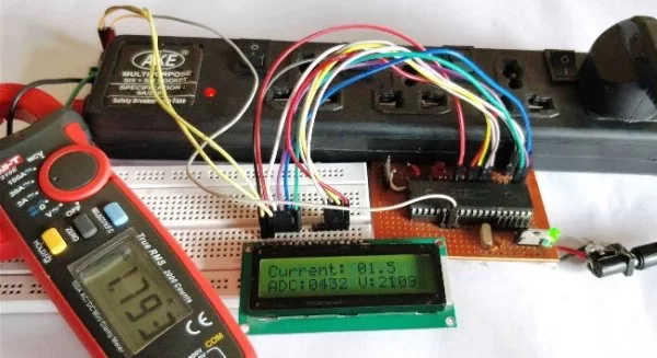
You can build this digital ammeter circuit on a breadboard or use a perf board. Here we have used the same perf Board which we have built for LED Blinking with PIC Microcontroller, as shown below:
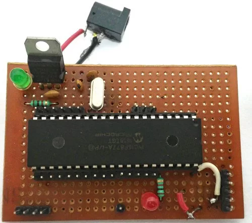
Note: It is not mandatory for you to build this board you can simply follow the circuit diagram and build you circuit on a bread board and use any dumper kit to dump your program into the PIC Microcontroller.
Simulation:
This current meter circuit can also be simulated using Proteus before you actually proceed with your Hardware. Assign the hex file of the code given at the end of this tutorial and click on play button. You should be able to notice the current on the LCD display. I have used a Lamp as an AC load, you can vary the internal resistance of the Lamp by clicking on it to vary the current flowing through it.
As you can see in the above picture, the Ammeter shows the actual current flowing through the Lamp which is around 3.52 A and the LCD shows the current to be around 3.6A. However in practical case we might get Error up to 0.2A. The ADC value and voltage in (mV) is also shown on the LCD for your understanding.
Programming the PIC Microcontroller:
As told earlier, the complete code can be found at the end of this article. The code is self explained with comment lines and just involves the concept of interfacing a LCD with PIC Microcontroller and Using ADC module in PIC Microcontroller which we have already covered in our previous tutorials of learning PIC Microcontrollers.
The value read from the sensor will not be accurate since the current is alternating and is also subjected to noise. Hence we read the ADC value for 20 Times and average it to get the appropriate current Value as shown in the code below.
We have used the same formulae which was explained above to calculate the voltage and Current value.
        for (int i=0; i<20;i++) //Read value for 20 Times
        {
        adc=0;
        adc=ADC_Read(4); //Read ADC
        Voltage = adc*4.8828; //Calculate the Voltage

        if (Voltage>=2500) //If the current is positive
              Amps += ((Voltage-2500)/18.5);

        else if (Voltage<=2500) //If the current is negative
              Amps += ((2500-Voltage)/18.5);
        }

        Amps/=20;  //Average the value that was read for 20 times
Since this project can also read AC current the current flow will be negative and positive as well. That is the value of the output voltage will be above and below 2500mV. Hence as shown below we change the formulae for negative and positive current so that we do not get negative value.
        if (Voltage>=2500) //If the current is positive
              Amps += ((Voltage-2500)/18.5);

        else if (Voltage<=2500) //If the current is negative
              Amps += ((2500-Voltage)/18.5);
Using a 30A current sensor:
If you need to measure current more than 5A you can simply buy a ACS712-30A module and interface it the same way and change the below line of code by replacing 18.5 with 0.66 as shown below:
        if (Voltage>=2500) //If the current is positive
              Amps += ((Voltage-2500)/0.66);

        else if (Voltage<=2500) //If the current is negative
              Amps += ((2500-Voltage)/0.66);
Working:
Once you have programmed the PIC Microcontroller and made your hardware ready. Simply power on the load and your PIC microcontroller you should be able to see the current passing through the wire displayed in your LCD screen.
NOTE: IF you are using a ASC7125A module make sure your load does not consume more than 5A also use higher gauge wires for current carrying conductors.
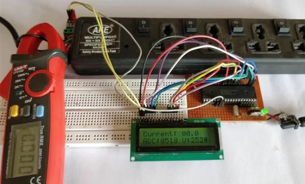
The complete working of the PIC microcontroller based ammeter project is shown in the Video below. Hope you got the project working and enjoyed doing it. If you have any doubts you can write them on the comment section below or post them on our forums.
Read more detail:Digital Ammeter Circuit using PIC Microcontroller and ACS712
- How does the ACS712 current sensor work?
It works by the Hall-effect: a hall sensor measures the magnetic field around a current carrying conductor and outputs a voltage proportional to the current with a 2500 mV offset at zero current. - Can this circuit measure both AC and DC current?
Yes, the ACS712 can measure both AC and DC current and the PIC code handles positive and negative swings by using the 2500 mV offset. - What microcontroller pin reads the sensor output?
The sensor Vout is connected to AN4, which is pin 7 of the PIC and read by the ADC module. - How is measurement noise reduced in the code?
The ADC is read 20 times and the results are averaged to reduce noise and improve accuracy. - What formula converts ADC readings to current for the 5A module?
Voltage (mV) = (ADC Value / 1023) * 5000; Current (A) = (Vout(mV) - 2500) / 185 (or in code using 18.5 scaled accordingly). - How do you adapt the code for a 30A ACS712 module?
Use the ACS712-30A sensor and replace 18.5 with 0.66 in the current calculation lines as shown in the article. - What power supply does the circuit use?
The setup uses a 12V power supply regulated to 5V via a 7805 for the circuit and sensor. - Where is the current displayed?
The measured current, ADC value, and voltage are displayed on the 16x2 LCD. - Can this circuit be simulated before building hardware?
Yes, the article suggests simulating the circuit in Proteus by assigning the provided hex file and observing LCD readings with a simulated load. - Are there safety or usage notes for the ACS712-5A module?
Yes: if using the ACS712-5A module ensure the load does not exceed 5A and use higher gauge wires for current-carrying conductors.