
Summary of 1-Chip 4-Channel PIC16F886 Data Logger
This project modifies Dan Gravatt’s Single Chip, Four Channel Datalogger by using a PIC16F886, employing the PIC hardware serial I/O, and adding an indicator LED and a mode switch. It logs sensor data to program flash using CCS C functions, with logging interval set in the code and memory start address adjustable to increase capacity. A LM35 temperature sensor and 7805 regulator with 9V battery are shown in the build. The PIC16F886 provides 8192 program flash words for storage.
Parts used in the PIC16F886 Four-Channel Data Logger:
- PIC16F886 microcontroller
- LM35 temperature sensor
- 7805 voltage regulator
- 9V battery
- Indicator LED
- Mode switch (logging/write serial)
- Serial connection hardware (pins 17 and 18 used)
- PCB or protoboard for circuit assembly
- Wiring and connectors
This project has only a few modifications from the “Single Chip, Four Channel Datalogger” article by Dan Gravatt in the 2008 January Issue of Nuts&Volts (page 42), so I won’t go into much detail.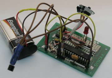
Below is the schematic. The changes from Dan’s datalogger are that I used the PIC16F886, which is pin-compatible with the PIC 16F876. I also used the PIC’s hardware serial I/O channels (pins 17 and 18) and I added an indicator LED that indicates logging in progress and the log interval (pin 22). The switch sets the mode between logging and writing data over the serial port.
The C data logger code is available here as is a hex file with 1 s log interval. I used the CCS compiler. This makes reading and writing program memory very straight forward with commands like write_program_eeprom( prog_mem_adr, value ) and read_program_eeprom(prog_mem_adr). The 16F886 has 8192 total program flash words. The total time of logging is determined by the delay setting at line 64 of main.c. Use a frequency counter at the indicator LED to set the desired logging interval. If you don’t add any lines to the code, you can increase the memory used for logging by setting START_ADR to the lowest open memory address.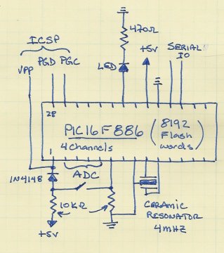 You can get this information with, e.g., the PICKit2 programming application or whatever your favorite PIC programmer provides.
Here’s the completed logger with a LM35 temperature sensor (suspended in the foreground) and a 7805 regulator (on the back left corner of the board) with a 9V battery attached.
For more detail: 1-Chip 4-Channel PIC16F886 Data Logger
- What microcontroller does this data logger use?
The project uses the PIC16F886 microcontroller. - Can this logger use hardware serial I/O?
Yes, the design uses the PIC’s hardware serial I/O on pins 17 and 18. - How is logging indicated?
An indicator LED shows logging in progress and the log interval on pin 22. - How do you switch between logging and sending data?
A switch selects between logging mode and writing data over the serial port. - What sensor is shown in the completed logger?
The completed logger shows an LM35 temperature sensor. - How is the logging interval set?
The logging interval is determined by the delay setting at line 64 of main.c in the provided C code. - How can you increase the amount of logged data without code changes?
Set START_ADR to the lowest open program memory address to increase memory used for logging. - How much program flash does the PIC16F886 have?
The PIC16F886 has 8192 total program flash words. - What tools or functions make reading/writing program memory easy?
The CCS compiler provides commands like write_program_eeprom and read_program_eeprom used in the project.
