If the piclist is an any indication the 16f877 seems to be the new favorite hobby microcontroller, a position that used to be occupied by the 16f84/16c84. Compared to is older brethren the 16f877 has much more to offer at around twice the price. As for all Microchip controllers the datasheet (pdf) and the MPLAB assembler IDE are available for free. (Microchip keeps changing its website, so when these links turn out to be invalid you might have to look around a little.)
The 16f877 supports three methods to get a program into the chip:
- HVP (High Voltage Programming) uses 12-14V on the reset (MCLR) pin to enable the serial programming mode via pins B6 and B7.
- LVP (Low Voltage Programming) uses B3 as (TTL level) enable input for the same serial programming mode.
- Self-programming uses a program executed by the 16f877 itself. This is the approach used by loader firmware.
HVP is always available. This is the programming method common to all PIC chips. LVP seems to be available on all new flash chips (16f87x, 16f62x). Self-programming is unique to the 16f877 and its close relatives (16f87x). LVP is available only when it is enabled by a bit in the fuses word (which can only be changed using HVP). LVP claims pin B3 as enable pin. By default a 16f877 is delivered with LVP enabled. (Loading the WLoader firmware disables it, so B3 is freed for use by the application.) Self-programming means that the 16f87x can program its own code FPROM, so – once you have loaded suitable application loader firmware in your target 16f87x – a simple serial interface to your PC is all you need to download and run an application. The pro’s and con’s of the three loading methods are summarized below.
| Method | Pro | Con | Comment |
| HVP | can be used with all PICs no dedicated pins |
needs 12-14V to enable, so programmer hardware is a bit complicated | best (only?) choice for production work |
| LVP | does not need 12-14V to enable, so only simple (TTL-only) hardware is needed can program fuses word (but not LVP enable) |
pin RB3 is dedicated to program-enable can not change LVP enable bit can be used with newer flash PICs only (16F87X, 16F62X) |
good choice for a very simple parallel port programmer |
| self-programming (bootloader) |
activation method can be choosen freely communication method can be choosen freely |
can not program fuses word can not be combined with code read-protection can be used with 16F87X PICs only the bootloader reduces the amount of code flash available for the application some compilers are not compatible with (some) bootloaders |
good choice for a simple serial port-based loader |
WLoader is yet another loader hardware / firmware / PC software set, but one that – in my opinion – has a very good set of features:
- either a true RS-232 level interface using a MAX232 (recommended), or a el-cheapo pseudo RS-232 serial interface, using only a few passive components (cheap, but for the brave ones only!)
- the serial interface use only one I/O pin
- the serial interface does not use the UART, so it can be assembled for any pin (except for the open-drain A4), and it can use non-inverting RS-232 hardware
- the serial interface pin can be re-used for most output purposes
- intelligent handling of application code that starts at 0000
- intelligent handling of the configuration fuses word
- protocol and DOS command line interface compatible with the Wisp programmer (e.g. load-verify-run-debug with one command line)
- protocol, firmware, DOS software and schematics are free
- occupies top 1K of the 8K code flash, so lower 7K is available for the application
Other free loader firmware and corresponding hardware and PC software that I know of are:
- Rick Farmer’s PICLOADER
- the HiTech loader
- Tony Nixton’s ROMzap (his site has disappeared, does anyone kwow where to get his stuff?)
- Shane Tolmie’s PIC16F87x and other bootloaders
- Karl Lunt’s PIC bootloader
Most of these loaders use the 16F877 build-in UART and are smaller than WLoader.
If neither WLoader nor any of the other bootloaders satisfies your particular needs (for instance because you want I2C, SPI or another exotic interface) do not hesitate to develop your own bootloader, it is not very difficult. Feel free to ask my assistance for such a project, but I will have to charge you a commercial rate – beside my hobbies I must make a living!
The block diagram shows the taget circuit as far as relevant for WLoader. The WLoader specific parts are a RS-232 send/receive combiner (a nice term for a few resistors), the RS-232 interface, and a remote reset circuit. The remote reset circuit can be omitted when the target circuit already has a manual reset (pushbutton switch), but it is very convenient to be able to reset the target (and hence activate WLoader) from the PC.
The block diagram also suggests how the circuits can be divided between the target itself and a download dongle. A production system could just provide the relevant signals on a 2×4 pin header, and rely on a download dongle that contains the remote reset and the RS-232 circuitry.
Note the resistor on the (single) line from the PIC used for communication. This resistor determines the level on the line when either the rest of the circuit or the PC is not connected, so in that case the application is started automatically when the PIC is reset.
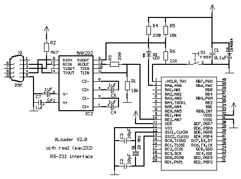
The preferred version of the WLoader hardware uses a MAX232 for RS-232 level conversion.
The right side of the circuit shows a fairly standard 16F877 target with reset (R5, R6, S1), power decoupling with reverse polarity protection diode (C1, D4), a 20 MHz crystal (Q1, C2, C3) and a LED (R4, D3). Note that conform good practice both sets of power pins of the 16F877 are connected. Except for the crystal (which must be 20 MHz) and the reset (see below) you can vary this part of the target circuit to suit your needs, or use what you already have in your design.
The WLoader specific stuff consists of a D9F connector and MAX232 level-converter (X1, IC2, C4..C7). The send-receive combiner is just R3. R1 is needed when the MAX232 can be removed from the circuit (when it is part of a download dongle) to provide a low level on the RE2 pin of the 16F877, so WLoader will start the application. R2 is needed when the MAX232 is a permanent part of the circuit, again to provide the low level on RE2, in this case when no PC is connected.
Note that the pull-up on the /MCLR pin is split in two (R5, R6) to allow a pull-down by the reset switch without shorting the R2OUT of the MAX232, and to reduce the load on the /MCLR pin when the target is programmed in-circuit.
This ‘el-cheapo’ version of the WLoader hardware uses a few resistors and a zener diode as RS-232 interface. It is shown here mainly because this was the original WLoader hardware. I recommend this version only to those who are enthousiastic about minimal-hardware solutions and can solve the problems that might occur. Don’t ask me for help.
The right side or the circuit is the same 16F877 target circuit as used with the MAX232. The only difference is that the /MCLR pull-up is one resistor.
The RS-232 interface (R2, D1, R7, R3) avoids current through the 16f877 protection diodes, which is outside Microchip’s operating specs and is rumored to cause all kinds of nasty effects. When the RS-232 input voltage is positive the D1 zener and R7 / R1 limit the voltage on the interface pin to somewhere between 4.7 V and Vcc. When the RS-232 input is negative the zener (now acting as diode) and the same resistors put a voltage on the interface pin that is close to zero. When nothing is connected to the RS-232 connector R1 keeps the 16f877 input high, which causes the loader to start the application when a reset occurs.
D2, R4, R5 and T1 provide a reset when the corresponding RS-232 line is high.
When the circuit is split between a dongle and the real target R1 must be included in the target so the application will be started on a reset.
The loader interface hardware can be part of the final circuit, and the loader interface pin can be shared with its operational function, but some attention must paid to its use:
- the loader interface pin must be pulled low (for the MAX232 version) or high (for the el-cheapo version) after a reset
- the PC’s RS-232 must be able to drive the loader interface pin
- during loading the loader interface pin is driven by the loader firmware.
When the target circuit must be kept as simple as possible the (real or el-cheapo) RS-232 interface, and the remote reset circuit can be put in a download dongle. In this case I recommend to use a 2×4 pin header (one pin removed as key) on the PCB and/or a D15M connector. When the pin assignment shown in the table is used the interface can be used both for HVP programming (Wisp programmer) and self-programming (WLoader).
| Key | Gnd | Mclr | E2 |
| B6 | B7 | Vcc | reserved |
2×4 programming connector (component view)
| pin | 1 | 2 | 3 | 4 | 5 | 6 |
| Use | Gnd | Vcc | B6 | B7 | Mclr | E2 |
D15F pin assignment
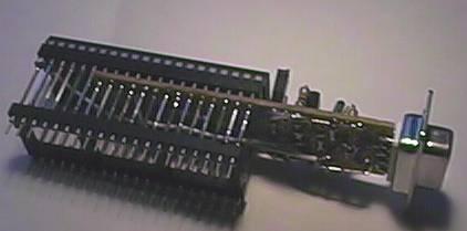
 The picture shows how I combined the WLoader hardware (old-style ‘el cheapo’ version) and a DB9 connector with a 16f877 in a wire-wrap socket, with a normal (round-pin) socket at the end of the wire wrap pins. The whole gadget can be plugged in where a 16f877 would fit and adds in-circuit downloading to a circuit. The 33k reset pull-up and a LED for power indication can be disabled by pulling two pin header jumpers (for low-current tests).
A reset (either manually or via the remote reset circuit) activates the loader. When no PC or download dongle is connected a resistor forces the interface pin to the opposite polarity of what it would be with the PC etc. connected. The loader detects this and will immediately activate the application. When a PC is connected the input is low (the RS-232 idle level is negative) and the loader will wait for instructions from the PC. The Wisp PC command-line tool can be used to download the application code, to verify the downloading, to start the application program, and provides a simple TTY interface that can be used to communicate with the application. The user must disconnect the RS-232 cable when the application program must run automatically after a reset.
The loader puts a goto instruction at addresses 0..2 to activate itself on reset. The user application instructions at these addresses are put at a location within the loader, and are executed before the jump to the rest of the user application program, starting at address 3. Hence the application loaded by the loader can be exactly the same as a stand-alone program downloaded to the 16f877. This trick will fail when the application program tries to use the instructions at the low addresses for something clever like
   $0000 reset_vector:         goto main
   $0001 delay_12:             call $+1
   $0002 delay_8:              call $+1
   $0003 delay_4:              ret
   $0004 interrupt_vector:     ...
Luckily most compilers are not that clever. For an overly-clever compiler you can try to let the application start with three NOPs.
The loader accepts instructions from the PC to write the configuration fuses and the code locations occupied by the loader. It does not actually perform the write, but does verify against the stored value, or in case of the configuration fuses word, against a copy of the actual fuses value. Hence the loading will not be hindered by the configuration fuses in the hex file, and a copy can be made of the application and configuration fuses and this copy can be downloaded using either the loader or a normal programmer. Note that in such a copy the loader will be disabled because the applications code for the addresses 0..2 is read, not the actual jump to the loader.
For more detail: WLoader – a 16f877 application loader
About The Author
Ibrar Ayyub
I am an experienced technical writer holding a Master's degree in computer science from BZU Multan, Pakistan University. With a background spanning various industries, particularly in home automation and engineering, I have honed my skills in crafting clear and concise content. Proficient in leveraging infographics and diagrams, I strive to simplify complex concepts for readers. My strength lies in thorough research and presenting information in a structured and logical format.
Follow Us:LinkedinTwitter